Download

1 / 18
360 likes | 1.47k Views
Semiconductor Strain Gages. Brandon Withers ECE 5320 Mechatronics Assignment #1. Outline. Major Applications Strain Theory Strain Gage Factors Unbonded and Bonded Strain Gages Semiconductor Strain Gages Principle of Measurement and Measurement Circuits

E N D
Semiconductor Strain Gages Brandon Withers ECE 5320 Mechatronics Assignment #1
Outline • Major Applications • Strain Theory • Strain Gage Factors • Unbonded and Bonded Strain Gages • Semiconductor Strain Gages • Principle of Measurement and Measurement Circuits • Strain Gage Specifications for the HBM SLB-700A/06
Reference List W. Tompkins, J. Webster, Interfacing Sensors To The IBM PC. Englewood Cliffs, NJ.:Prentice Hall Inc., 1988. National Instruments, (2004, Feb. 21). “Measuring Strain with Strain Gauges” (2004) [Online]. Available: http://zone.ni.com/devzone/conceptd.nsf/webmain/C83E9B93DE714DB08625686600704DB1?OpenDocument Omega Engineering, (2004, Feb. 21). “The Strain Gage” (2003) [Online]. Available: http://www.omega.com/literature/transactions/volume3/strain.html HBM, (2004, Feb. 21). “SLB-700A/06 – Strain Transducer” (2003) [Online]. Available: http://www.ae.utexas.edu/courses/ase389/midterm/larry/sircxsar.htm
To Explore Further • Strain Gage Tutorials -- http://www.omega.com/techref/strain-gage.html -- http://www.vishay.com/company/brands/measurements- group/guide/indexes/tn_index.htm • Manufacturers of Strain Gages and Accessories -- http://www.hbm.com/en/ -- http://www.smdsensors.com/ -- http://www.omega.com -- http://www.vishay.com • Useful Site With Many Strain Gage Links -- http://users.telenet.be/educypedia/electronics/sensorsdis.htm
Major Applications • Force, Torque and Pressure Transducers • Load Cells in Commercial Scales, Tank and Vessel Weighing • Bathroom and Kitchen Scales • Stress Analysis Tests • Measurements of deflection angles of control surfaces (helicopter blades, wing flaps, elevators, etc.)
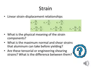
Strain Theory Strain is the amount of deformation of a body due to an applied force or in other words strain is the fractional change in length shown in the figure above. Strain can be positive (tensile) or negative (compressive). “Measuring Strain with Strain Gauges”
Strain Theory (cont.) For a wire of cross-sectional area A, resistivity ρ, and length L the resistance is given by When the wire is stretched, the cross-sectional area A is reduced, which causes the total wire resistance to increase. In addition, since the lattice structure is altered by the strain, the resistivity of the material may also change, and this, in general, causes the resistance to increase further. Both effects are included in the following equation: = fractional resistance change = Poisson’s ratio = fractional change in length = fractional change in resistivity
Strain Theory (cont.) To provide a means of comparing the performance of various gage materials, the gage factor, or strain sensitivity, of a gage is defined as Higher gage factors are generally more desirable because the higher the gage factor the higher the resolution of the strain gage.
Strain Gage Factors “The Mechatronics Handbook” Semiconductor materials such as Silicon and Germanium are used for strain gages because of their high gage factors.
Unbonded and Bonded Strain Gages The unbonded strain gage consists of a wire stretched between two points in an insulating medium such as air. Four gages are normally connected in a Wheatstone bridge circuit and arranged so that two gages are lengthened and two shortened by the displacement. A bonded strain-gage element, consisting of a metallic wire, etched foil, vacuum-deposited film, or semiconductor bar, is cemented to the strained surface. “The Mechatronics Handbook”
Semiconductor Strain Gages • Strain-gage technology advanced in the 1960s with the introduction of the semiconductor strain-gage elements • Silicon gages are formed from single-crystal silicon whose orientation and doping are the most important design parameters. The gage factor depends on the resistivity (determined by the doping) and the crystal orientation. • Bonded semiconductor gages are made by slicing sections from specially processed silicon crystals and are available in both n and p types. The high gage factor is accompanied by high-temperature sensitivity, nonlinearity, and mounting difficulties. • Diffused semiconductor gages utilize the diffusion process employed in integrated-circuit manufacture. This type of construction may allow lower manufacturing costs in some designs, since a large number of devices can be made on a single silicon wafer. The deviation from linearity is approximately 1%
Ideal Strain Gage vs. Diffused Strain Gage Ideal Strain Gage Properties • Small in size and mass • Low in cost • Accurate and repeatable • Easily attached • Perfect output signal • Infinite pressure range • Highly sensitive to strain but insensitive to ambient or process temperature variations • Diffused Strain Gage Properties • Small in size and mass • Low in cost • Accurate and repeatable • Tricky to attach • High output signal • Wide pressure range • Highly sensitive to strain but limited to moderate-temperature applications and requires temperature compensation
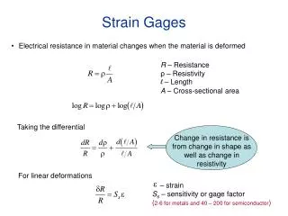
Principle of Measurement Mechanical loading produces a change of length in the measurement object, which is conveyed to the strain gauge. Because there is a change in length, the electrical resistance of the applied strain gauge also changes in proportion to the strain. If there is excitation voltage, the circuit supplies an output signal proportional to the change in resistance and therefore also proportional to the change in length. A carrier frequency or DC amplifier suitable for strain gauges enables measurement signal evaluation to continue.
Measurement Circuits • Common Wheatstone bridge circuit, null when R1/R4=R2/R3 • All resistances equal but one is variable by a factor, (1+x), where x is a fractional deviation around zero, as a function of strain. Sufficiently linear for small values of x. • Output doubles if two identical variable elements can be used • Two variable resistors increase while two decrease. Commonly used with two identical two-element strain gages attached to opposite faces of a thin beam to measure bending. The output is four times the output for a single-element bridge, and it is linear with x. • Uses a zero-centered potentiometer to constitute two adjacent arms. • Op amp forces the bridge to be balanced. It has good linearity and very low output impedance, thus making the output measurement easier and more accurate. “The Mechatronics Handbook”
Strain Gage Specifications HBM SLB-700A/06 Key Features • For Monitoring strain in statically and dynamically loaded units such as cranes, presses and roll stands • Simply bolted into place • Stainless steel • Protected from harmful environmental effects • Inexpensive • Strain gauge full bridge “SLB-700A/06 – Strain Transducer”
HBM SLB-700A/06 Specifications “SLB-700A/06 – Strain Transducer”
HBM SLB-700A/06 Specifications “SLB-700A/06 – Strain Transducer”
HBM SLB-700A/06Mounting The SLB700A strain transducer is attached to the measurement object by means of four normal M6 hexagon socket screws (e.g. DIN 912). We recommend screws of resistance class 12.9, which should be tightened in a sequence of diagonal opposites, using a tightening torque of 16 N⋅m. Alternatively, use screws of resistance class 8.8 and a tightening torque of 8 N⋅m. The strain transducer must not be mounted in the central, offset area and it must be installed free from distortion. “SLB-700A/06 – Strain Transducer”