Shearing Strain
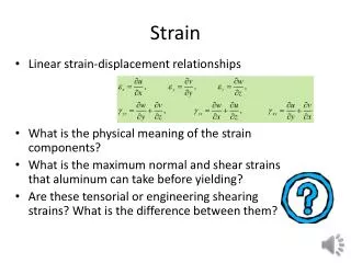
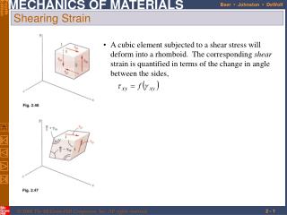
Shearing Strain. A cubic element subjected to a shear stress will deform into a rhomboid. The corresponding shear strain is quantified in terms of the change in angle between the sides,. 2 - 1. Find:. Initial Plate. Deformed Plate.

Shearing Strain
E N D
Presentation Transcript
Shearing Strain • A cubic element subjected to a shear stress will deform into a rhomboid. The corresponding shear strain is quantified in terms of the change in angle between the sides, 2 - 1
Find: Initial Plate Deformed Plate Given:A metallic rectangular plate of length L and width L/2 is shown in figure. When the plate is subjected to stresses acting along the edge faces, it distorts into a parallelogram.
Let the origin of the coordinates be located at the corner A. The shearing strain equals the change in angle between the positive x and y direction. In as much as deformations are small we can write, Hence, The plus sign indicates that the angle BAD has decreased.
A thin triangular plate ABC is uniformly deformed into a shape of ABC’, as shown by dashed lines in fig. The edge AB is rigidly attached to the frame .The deformed edges AC’=BC’ are straight lines.
= The change in length OC is Referring to the figure The length of deformed edges are-
The angle ACB becomes- The change in right angle is then 90-89.943=0.0570
A 0.4m by 0.4 m square ABCD is drawn on a tin panel or flat plate of an aircraft prior to loading. Subsequent to loading ,the square has the dimensions shown by dashed lines. The average values of two dimensional strain components at corner A `
A plot of shear stress vs. shear strain is similar to the previous plots of normal stress vs. normal strain except that the strength values are approximately half. For small strains, where G is the modulus of rigidity or shear modulus. Shearing Strain
For a slender bar subjected to axial loading: • The elongation in the x-direction is accompanied by a contraction in the other directions. Assuming that the material is isotropic (no directional dependence), • Poisson’s ratio is defined as Poisson’s Ratio
With these restrictions: Generalized Hooke’s Law • For an element subjected to multi-axial loading, the normal strain components resulting from the stress components may be determined from the principle of superposition. This requires: • 1) strain is linearly related to stress2) deformations are small
Relative to the unstressed state, the change in volume is • For element subjected to uniform hydrostatic pressure, • Subjected to uniform pressure, dilatation must be negative, therefore Dilatation: Bulk Modulus
A cubic element subjected to a shear stress will deform into a rhomboid. The corresponding shear strain is quantified in terms of the change in angle between the sides, • A plot of shear stress vs. shear strain is similar to the previous plots of normal stress vs. normal strain except that the strength values are approximately half. For small strains, where G is the modulus of rigidity or shear modulus. Shearing Strain
Example 2.10 • SOLUTION: • Determine the average angular deformation or shearing strain of the block. • Apply Hooke’s law for shearing stress and strain to find the corresponding shearing stress. A rectangular block of material with modulus of rigidity G = 620 MPa is bonded to two rigid horizontal plates. The lower plate is fixed, while the upper plate is subjected to a horizontal force P. Knowing that the upper plate moves through 1.00 mmunder the action of the force, determine a) the average shearing strain in the material, and b) the force P exerted on the plate. • Use the definition of shearing stress to find the force P.
Determine the average angular deformation or shearing strain of the block. • Apply Hooke’s law for shearing stress and strain to find the corresponding shearing stress. • Use the definition of shearing stress to find the force P.
The above figure shows a square element ABCD, sides of unstrained length 2units under the action of equal normal stresses σ,tension and compression. Then it has been shown that the element EFGH is in pure shear of equal magnitude σ.
From the above figure, Linear strain in direction EG=σ/E + vσ/E say, ε = (1+v)σ/E -------------------------→ (1) Linear strain in direction HF = -σ/E - vσ/E = - ε Hence the strained lengths of EO and HO are 1+ε and 1-ε respectively.
The shear strain is ø = σ/G --------------------------------------→ (2) on the element EFGH and the angle EHG will increase to ∏/2 +ø. Angle EHO is half this value, i.e. ∏/4 +ø/2. Considering the triangle EOH, tan EHO = EO/HO i.e. tan ( ∏/4+ø/2) = (1+ε)/(1-ε)
Expanding, (1+ε)/(1-ε) = (tan ∏/4 +tan ø/2) / (1- tan ∏/4 . tan ø/2) = (1+ ø/2) / (1- ø/2) (approx.) since tan ∏/4 = 1 and tan ø/2 = ø/2 for small angles Clearly ε = ø/2 and by substitution for ε and ø from (1) and (2),we get (1+v)σ/E = σ/2G Rearranging , E = 2G(I+v)
Components of normal and shear strain are related, Relation Among E, n, and G • An axially loaded slender bar will elongate in the axial direction and contract in the transverse directions. • An initially cubic element oriented as in top figure will deform into a rectangular parallelepiped. The axial load produces a normal strain. • If the cubic element is oriented as in the bottom figure, it will deform into a rhombus. Axial load also results in a shear strain.
Sample Problem 2.5 • A circle of diameter d = 225 mm is scribed on an unstressed aluminum plate of thickness t = 20 mm Forces acting in the plane of the plate later cause normal stresses sx = 82.7 MPa and sz = 138 MPa. • For E = 69 GPa and n = 1/3, determine the change in: • the length of diameter AB, • the length of diameter CD, • the thickness of the plate, and • the volume of the plate.
SOLUTION: • Apply the generalized Hooke’s Law to find the three components of normal strain. • Find the change in volume • Evaluate the deformation components.
Normal stresses and strains are related by Hooke’s Law but with directionally dependent moduli of elasticity, • Transverse contractions are related by directionally dependent values of Poisson’s ratio, e.g., Composite Materials • Fiber-reinforced composite materials are formed from lamina of fibers of graphite, glass, or polymers embedded in a resin matrix. • Materials with directionally dependent mechanical properties are anisotropic.
Saint-Venant’s Principle • Loads transmitted through rigid plates result in uniform distribution of stress and strain. • Concentrated loads result in large stresses in the vicinity of the load application point. • Stress and strain distributions become uniform at a relatively short distance from the load application points. • Saint-Venant’s Principle:Stress distribution may be assumed independent of the mode of load application except in the immediate vicinity of load application points.
Stress Concentration • Before ripping a piece of cloth a tailor puts a small cut with scissors. • Its easier to tear a piece of paper when it has a small cut in it. • Why are the door and window openings in aero-planes and ships rounded ?
Stress Concentration: Hole Discontinuities of cross section may result in high localized or concentrated stresses.
Example 2.12 • SOLUTION: • Determine the geometric ratios and find the stress concentration factor from Fig. 2.64b. Determine the largest axial load P that can be safely supported by a flat steel bar consisting of two portions, both 10 mm thick, and respectively 40 and 60 mm wide, connected by fillets of radius r = 8 mm. Assume an allowable normal stress of 165 MPa. • Find the allowable average normal stress using the material allowable normal stress and the stress concentration factor. • Apply the definition of normal stress to find the allowable load.
Determine the geometric ratios and find the stress concentration factor from Fig. 2.64b. • Find the allowable average normal stress using the material allowable normal stress and the stress concentration factor. • Apply the definition of normal stress to find the allowable load.
What are composites? • Why fibers are strong ?
Analysis of plastic deformations is simplified by assuming an idealized elastoplastic material • Deformations of an elastoplastic material are divided into elastic and plastic ranges • Permanent deformations result from loading beyond the yield stress Elastoplastic Materials • Previous analyses based on assumption of linear stress-strain relationship, i.e., stresses below the yield stress • Assumption is good for brittle material which rupture without yielding • If the yield stress of ductile materials is exceeded, then plastic deformations occur
Maximum stress is equal to the yield stress at the maximum elastic loading • As the loading increases, the plastic region expands until the section is at a uniform stress equal to the yield stress Plastic Deformations • Elastic deformation while maximum stress is less than yield stress • At loadings above the maximum elastic load, a region of plastic deformations develop near the hole
Residual Stresses • When a single structural element is loaded uniformly beyond its yield stress and then unloaded, it is permanently deformed but all stresses disappear. This is not the general result. • Residual stresses will remain in a structure after loading and unloading if • only part of the structure undergoes plastic deformation • different parts of the structure undergo different plastic deformations • Residual stresses also result from the uneven heating or cooling of structures or structural elements
A cylindrical rod is placed inside a tube of the same length. The ends of the rod and tube are attached to a rigid support on one side and a rigid plate on the other. The load on the rod-tube assembly is increased from zero to 25 kN and decreased back to zero. • draw a load-deflection diagram for the rod-tube assembly • determine the maximum elongation • determine the permanent set • calculate the residual stresses in the rod and tube. Example 2.14, 2.15, 2.16
Example 2.14, 2.15, 2.16 • Draw a load-deflection diagram for the rod-tube assembly
The rod-tube assembly unloads along a line parallel to 0Yr b,c) determine the maximum elongation and permanent set Example 2.14, 2.15, 2.16 • At a load of P = 25 kN, the rod has reached the plastic range while the tube is still in the elastic range
Example 2.14, 2.15, 2.16 • Calculate the residual stresses in the rod and tube. Calculate the reverse stresses in the rod and tube caused by unloading and add them to the maximum stresses.
Managing thermal stress • Most structures, small or large, are made of two or more materials that are clamped, welded or otherwise bonded together. This causes problems when temperatures change. • Railway track will bend and buckle in exceptionally hot weather (steel, high α, clamped to mother earth with a much lower α). • Bearings seize, doors jam. • Thermal distortion is a particular problem in equipment designed for precise measurement or registration like that used to make masks for high-performance computer chips, causing loss of accuracy when temperatures change.
All of these derive from differential thermal expansion, which, if constrained (clamped in a way that stops it happening) generates thermal stress. • As anexample, Many technologies involve coating materials with a thin surface layer of a different material to impart wear resistance, or resistance to corrosion or oxidation. The deposition process often operates at a high temperature. On cooling, the substrate and the surface layer contract by different amounts because their expansion coefficients differ and this puts the layer under stress.
This residual stress calculated as follows. • Think of a thin film bonded onto a component that is much thicker than the film, as in Figure. • First imagine that the layer is detached, as in Figure. A temperature drop of ∆T causes the layer to change in length by Fig: Thermal stresses in thin films arise on cooling or heating when their expansion coefficients differ. Here that of the film is α1 and that of the substrate, a massive body, is α2.
Meanwhile, the substrate to which it was previously bonded contracts by . If the surface layer shrinks more than the substrate. • If we want to stick the film back on the much-more-massive substrate, covering the same surface as before, we must stretch it by the strain • This requires a stress in the film of
The stress can be large enough to crack the surface film. The pattern of cracks seen on glazed tiles arises in this way. • So if you join dissimilar materials you must expect thermal stress when they are heated or cooled. The way to avoid it is to avoid material combinations with very different expansion coefficients. • Avoiding materials with α mismatch is not always possible. As example, joining glass to metal—Pyrex to stainless steel, say—a common combination in high vacuum equipment. Their expansion coefficients for Pyrex (borosilicate glass), α =4 x 10⁻⁶/K; for stainless steel, α =20x 10-6/K: a big mismatch. • Vacuum equipment has to be ‘baked out’ to desorb gases and moisture, requiring that it be heated to about 150°C, enough for the mismatch to crack the Pyrex.