Download
1 / 40
410 likes | 542 Views
Learn gap analysis, traffic signals, conflict points, and more for intersection design to enhance safety and traffic flow.

E N D
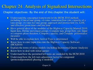
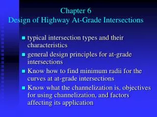
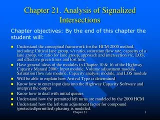
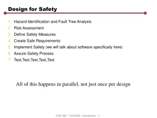
Chapter objectives covered in CE361: By the end of this chapter the student will be able to: Chapter 8. Design of Intersections for Safety and Efficiency Find the critical gap for an unsignalized intersection approach (given data of accepted and rejected gaps) Analyze the sight distances at an intersection for possible installation of stop or yield signs Determine when an intersection warrants the installation of a traffic signal Design signal settings for intersections so that drivers will not face a dilemma zone Estimate the stopped delay for an approach to an intersection (Not covered in CE361; extensively covered in CE562). Chapter 8
8.1 Analysis of Non-signalized Intersections By the end of this section, the student will be able to... • Objectives of 8.1 • Determine gaps in traffic that are acceptable to motorists (critical gaps) • Determine whether to install a yield sign or stop sign, based on critical approach speed 9 Chapter 8
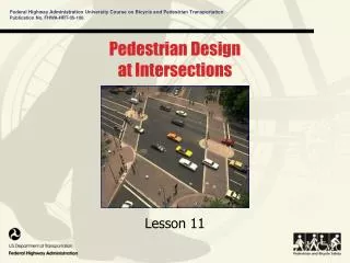
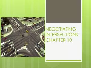
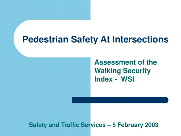
Safety – Reduce Conflict Points • Right of way needs to be assigned to reduce potential conflicts and crashes. • See the next slide to see how many potential conflict points exists in a T and a 4-leg unsignalized intersection. Chapter 8
Conflict points at unsignalized intersections T intersection 4-leg intersection Total = 32 Crossing = 3 Merging = 3 Diverging = 3 Total = 9 Chapter 8
Source - NHI Course 15255 Conflict Points with Raised Median can reduce conflict points Raised median TWLTL Undivided Chapter 8
Conflict Points with a Roundaboutanother way to reduce conflict points Source: www.alaskaroundabouts.com Chapter 8
8.1.1 Gap acceptance Observe Traffic (count cars!Measure time gaps or headways!) • Think about it: • How long a gap in the cross traffic does a driver need before he or she will attempt to make a right turn? • Will the length of the gap vary from driver to driver? • How would you collect data to answer these questions? Chapter 8
8.1.1 Gap acceptance (cont) Gap First, terminology... Lag • Headway – time elapsed between the front bumper of one vehicle and the front bumper of the following vehicle passing a given point • Gap – time elapsed between the rear bumper of one vehicle and the front bumper of the following vehicle passing a given point • Lag – time elapsed between the arrival of a minor-street vehicle ready to move into the major street and the arrival of the front bumper of the next vehicle in the major traffic stream • Accepted gap or lag – gap or lag that the driver of a minor street vehicle uses to move into the major street • Rejected gap or lag – gap or lag that the driver of a minor street vehicle waiting to enter the major street does not accept • Untested gap – no minor street vehicle was present • Critical gap – the minimum size gap that a particular driver will accept Chapter 8
Events in gap acceptance analysis LH = LT veh at Head of minor st. queue (ready to begin turning movement) RH = RT veh at Head of minor st. queue (ready to begin turning movement) MN = Major st. vehicle on the Near side MF = Major st. vehicle on the Far side LA = LH vehicle accepts the gap/lag RA = RH vehicle accepts the gap/lag Chapter 8
Example 8.1 Key for understanding this table Check the arrival of MN after the arrival of RH. Note that in this table, gap and headway are considered interchangeable. RH1 RH 2 RH 1 RA 2 MN RH 3 MN RA1 RA 3 MN MN Chapter 8
Gap analysis data (p.8.5) Sample calculations: Chapter 8 Table 8.1 data. 2/115=0.017 204/217=0.940
tc Mr. Raff’s method simplified The gap for which the number of accepted gaps shorter than it is equal to the number of rejected gaps longer than it. Mr. Raff Assumption: Between 5 and 6 seconds, the two lines are straight. R(t1) A(t2) A(t1) R(t2) Chapter 8
8.1.2 Stop, Yield, or No Control at Urban Intersections Hierarchy of intersection control: Intersection Control Options: How much judgment can drivers safely exercise to avoid collisions? Three levels of control are available. Chapter 8
YIELD Warrants for YIELD sign(Not in the text) The YIELD sign may be warranted (MUTCD 2009): • On approaches to a through street or highway where conditions are such that a stop is not always required. • At a second crossroad of a divided highway, where the median width is 30ft or greater. A STOP sign may be installed at the entrance to the first roadway of a divided highway, and a YIELD sign may be installed at the entrance to the second roadway. • On a channelized turn lane that is separated from the adjacent travel lane by an island, even if the adjacent lanes at the intersection are controlled by a highway traffic control signal or by a STOP sign. • At an intersection where a special problem exists and where engineering judgment indicates that the problem is susceptible to correction by use of a YIELD sign. • Facing the entering roadway for a merge-type movement if engineering judgment indicates that the control is needed because acceleration geometry and/or sign distance is not sufficient for merging traffic operation. Chapter 8
Warrants for two-way STOP sign(not in the text) Because the STOP sign causes a substantial inconvenience to motorists, it should be used only where warranted. A STOP sign may be warranted where one or more of the following conditions exist (MUTCD 2009): • The vehicular traffic volume on the through street or highway exceed 6,000 veh/day. • A restricted view exists that requires road users on the minor street approach to stop in order to adequately observe conflicting traffic on the through street or highway. • Crash records indicate that 3 or more crashes susceptible to correction by installation of a STOP sign have been reported within a 12-month period, or that 5 or more such crashes have been reported within a 2-year period. Such crashes include right-angle collisions involving road users on the minor street approach failing to yield the right-of-way to traffic on the through street or highway. Chapter 8
The critical approach speed (CAS) method • If the computed speed is between 10 and 15 mph, a YIELD sign is appropriate. • If the computed speed is less than 10 mph, a STOP sign must be installed • At computed speeds higher than 15 mph, the CAS does not by itself justify a STOP or YIELD sign. Further analyses may be needed. (MUTCD has a set of warrants for Yield and Stop sign. Approach speed is not the only concern as shown in the previous two slides.) After checking the need for a yield or stop sign, check the intersection sight distance (ISD) for vehicles on the major street. If ISD is inadequate, stop signs on the major street may be called for. (see page 8.10 for tc values. tc= 7.5 sec for passenger cars, tc= 9.5 for single unit trucks, and tc= 11.5 sec for combination trucks to turn into the major street. LT is more critical.) ISD = 1.47*V*tc Chapter 8
The CAS Method a”, b”, c”, and d” are measured at the site. a’, b’, c’, and d’ are computed as follows: • a’ = 12 ft with parking, a’ = 6’ without parking. • b’ = min{½W + 3 ft; W – 12 ft} • c’ = 12 ft with parking, c’ = 6’ without parking. • d’ = ½W + 3 ft 3 ft = distance between the centerline and the driver’s head. 1/2W = distance between the center line and the curb W = street width Chapter 8
The CAS Method (cont.) Find: • Place points (b,a) and (c,d) in Fig 8.6. • Extend lines starting from the 85th-percentile speed on Main St., passing though the two points. • Read Minor street speed from B scale. • Use the lower speed to make a decision: <= 10 mph – stop sign; 10 <= speed <=15 mph – yield sign. Otherwise, needs further study. We will walk though Example 8.2. Chapter 8
8.2 Signal Warrants & Stopping Distance at Signalized Intersections • Objectives of 8.2 • Determine when to install a traffic signal. • Determine whether a dilemma zone exists on the approach to a signalized intersection By the end of this section, the student will be able to... Chapter 8
8.2 Signal Warrants & Stopping Distance at Signalized Intersections • When should traffic signals be installed? • When do signal timings create a hazardous situation for drivers 8.2.1 Warrant Analysis MUTCD 2009 has 9 warrants for a traffic signal. They are guides, not specifications. Use professional judgments. • Warrant 1: Eight-hour vehicular volume • Warrant 2: Four-hour vehicular volume • Warrant 3: Peak hour • Warrant 4: Pedestrian volume • Warrant 5: School crossing • Warrant 6: Coordinated signal system • Warrant 7: Crash experience • Warrant 8: Roadway network • Warrant 9: Intersection Near a Highway-Rail Crossing Signals Covered in detail in CE562. Chapter 8
Signal warrant 1A: 8-hour volume(Table 8.2 in your textbook) Min. vehicle volume: Principal factor is the intersection traffic volume. Must satisfy for each of any 8 hour of an average day (threshold values). • May reduce the values by 30% if the 85th percentile speed on the major approach is greater than 40 mph or population is less than 10,000 (built-up area of isolated community). Chapter 8
Signal warrant 1B(This is not in your textbook.) Interruption of continuous traffic:The volume requirements must be met for each of any 8 hours of an average day. • May reduce the values by 30% if the 85th percentile speed on the major approach is greater than 40 mph or population is less than 10,000 (built-up area of isolated community). Chapter 8
Signal warrant 1C(This is not in your textbook.) Combination of warrants: Only in exceptional cases. When none of them are satisfied but when the first two warrants, 1A and 1B, of Warrant 1 are satisfied to the extent of 80% of the stipulated volumes. Chapter 8
Example 8.3 Chapter 8 We will walk through this example. Problem 8.8 is an extension of this example.
8.2.2 Reacting to a Changing Traffic Signal – a story of “dilemma zone” “..., the term “amber” has been changed to “yellow,” and the yellow interval simply means “the red interval is coming.” The preferred reaction is to try to stop. However, it is possible that there is not sufficient distance for the car to stop, and the car would be in the intersection when the cross traffic gets the green light. The driver could be accused of “running the red light.” Note that currently “running the red light” means the vehicle enters the intersection after the red light was turned on. Once the vehicle is in the intersection, you are not “running the red light” when the cross traffic gets the green light. Most of the signal has an all-red interval after the yellow interval, which was meant to clear the intersection for conflicting movements. Chapter 8
L Safely stop at or before the stop bar or clear the intersection & dilemma zone Cannot clear but can safely stop Cannot safely stop but can clear To safely stop: To safely clear: Dilemma zone: Cannot stop or cannot finish crossing (XS>D) Chapter 8 Usually it is assumed the car will not accelerate (conservative estimate).
L Safely stop at or before the stop bar or clear the intersection & dilemma zone (using SSD formula) Cannot safely stop but can clear Cannot clear but can safely stop To safely stop: To safely clear: Dilemma zone: Cannot stop or cannot finish crossing (XS>D) Chapter 8 Usually it is assumed that the car will not accelerate (conservative estimate).
Eliminating the dilemma zone When D = Xs, there is no dilemma zone - at least theoretically. Chapter 8
Solution to Example 8.4 using SSD formula The minimum distance needed to stop Xc is: XS = votr + v02/[2*g(f±G)] = 30*1.47*1.5 + (30*1.47)2/[2*32.2*0.35] = 66.15 + 86.28 = 152.4 ft (G = 0, flat profile) The maximum distance from which the vehicle can safely clear the intersections is: D = votY – (W + L) = 30*1.47*4 – (60 + 16) = 176.4 – 76 = 100.4 ft XS > D (152.4 ft > 100.4 ft), hence a dilemma zone exists. Its length is 152.4 ft – 100.4 ft = 52 ft. The driver’s claim cannot be dismissed, but now the issue becomes whether the vehicle was in the dilemma zone when the light changed to yellow. The difference is caused by use of fixed f value. f value varies because f = a/g. f = 10/32.2 = 0.31 instead of 0.35. Chapter 8
Solution to Example 8.5 using SSD formula A) Since tY remains to be 4 seconds, AR = 1.18 seconds B) Solving for v0, vo = 79.93 ft/s or 21.40 ft/sec or vo = 54.4 mph or 14.6 mph (depends on the location of the vehicle from the stop bar when the light turns yellow.) The differences are caused by use of fixed f value. f value varies because f = a/g. f = 10/32.2 = 0.31 instead of 0.35. Chapter 8
8.3 Analysis of Signalized Intersection By the end of this section, the student will be able to... • Objectives of 8.3 • Summarize a signal timing plan for a given intersection in a concise format (8.3.1). • Use time-space diagram to analyze systems of traffic signal settings (8.3.2) • Why actuated signals are superior? (8.3.3) – Just its concept is presented in CE361. • Delay estimation (8.3.4) (Section 8.3.4 is not covered in CE361; they are discussed in detail in CE562 Traffic Engineering) Chapter 8
8.3 Analysis of Signalized Intersection 8.3.1 Traffic signal timing Cycle length Phase Interval Change interval All-red interval (clearance interval) Controller Chapter 8
Offset Master controller Terms related to signal timing (cont) • Phase = A signal phase consists of a green interval (G), plus the change (Y) and clearance intervals (AR) that follow it. It is a set of intervals that allows a designated movement or set of movements to follow and to be safely halted before release of a conflicting set of movements. • Offset = The difference between the time when the upstream intersection turns green and the downstream intersection turns green Chapter 8
Table 8.4 shows a traffic signal-timing form Cycle length (C) = 75 seconds You can calculate interval lengths from the given G-Y-R data, but a diagram like this gives you a clearer picture of what’s happening in the cycle. Look at these diagrams as you read the explanation of the timing form in the text (Last paragraph of p.8.20, Example 8.6). Chapter 8
8.3.2 Time-Space Diagrams T-S diagram: A scaled chart that shows trajectories of vehicles traveling downstream or upstream • Stopped (distance/time = 0/time = 0 speed) • Traveling downstream at a speed • Stopped again • Traveling downstream again Example 8.7 Chapter 8
Time-space diagram for signal coordination(Fig 8.14 is for Example 8.7) Once the timing design of each signal is completed, offsets of the signals can be adjusted to achieve the speed and green band desired. But depending on the block length and timing, you may not be able to get exactly what you want. Detail: But, don’t worry this part Chapter 8
Example 8.7 Chapter 8
Example 8.7 by Synchro 7 software Chapter 8
8.3.3 Actuated Traffic Signals • Pretimed signals operate with constant cycle lengths, phase sequence, and interval timings Capacity with a pretimed controller is constant. Wasted green Queue forming • When demand varies significantly from time to time, either green time is wasted or queue forms. • In a coordinated system, however, all signals must operate on a single fixed cycle length to maintain offsets and progression patterns Actuated controllers with variable cycle lengths are not good for such cases. “Actuated” only in green time intervals is OK for coordinated systems. Chapter 22