Download
1 / 18
180 likes | 209 Views
Learn how the PCV system works in engines, regulating air flow to prevent issues like rough idle or stalling. Explore diagrams and components.

E N D
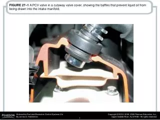
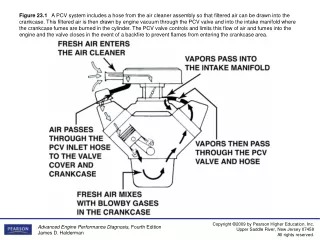
Figure 23.1A PCV system includes a hose from the air cleaner assembly so that filtered air can be drawn into the crankcase. This filtered air is then drawn by engine vacuum through the PCV valve and into the intake manifold where the crankcase fumes are burned in the cylinder. The PCV valve controls and limits this flow of air and fumes into the engine and the valve closes in the event of a backfire to prevent flames from entering the crankcase area.
Figure 23.2A dirty PCV vent filter inside the air cleaner housing. The air enters the crankcase through this filter and then is drawn into the engine through the PCV valve.
Figure 23.3Spring force, crankcase pressure, and intake manifold vacuum work together to regulate the flow rate through the PCV valve.
Figure 23.4 Air flows through the PCV valve during idle, cruising, and light-load conditions.
Figure 23.5Air flows through the PCV valve during acceleration and when the engine is under a heavy load.
Figure 23.7A visual inspection found this deteriorated PCV vacuum hose.
Figure 23.8A typical PCV valve. A defective or clogged PCV valve or hose can cause a rough idle or stalling problem. Because the air flow through the PCV valve accounts for about 20% of the air needed by the engine at idle, use of the incorrect valve for an application could have a severe effect on idle quality.
Figure 23.9A typical PCV valve installed in a rubber grommet in the valve cover.
Figure 23.10A water manometer being used to check for a slight vacuum when testing at the oil dipstick tube
Figure 23.11A typical belt-driven air pump.Air enters through the revolving fins. These fins act as a moving air filter because dirt is heavier than air and therefore the dirt in the air is deflected off the fins at the same time the air is drawn into the pump.
Figure 23.12aWhen the engine is cold and before the oxygen sensor is hot enough to reach closed loop, the air flow is directed to the exhaust manifold(s) through one-way check valve(s). These valves keep exhaust gases from entering the switching solenoids and the air pump itself.
Figure 23.12bWhen the engine achieves closed loop, the air flows from the pump, is directed to the catalytic converter, and then moves through a check valve.
Figure 23.13An AIR exhaust check valve between the rubber air hose and the metal discharge tubes.
Figure 23.14Exhaust check valves in the AIR system allow air to flow in only one direction.
Figure 23.15A typical belt-driven air pump used on an older model Chevrolet Corvette.
Figure 23.16The air pump supplies air to the exhaust port of each cylinder. Unburned HCs are oxidized into CO2 and H2O and CO is converted to CO2.
Figure 23.17A typical electric motor-driven secondary air injection (SAI) pump. This unit is on a Chevrolet Corvette and only works when the engine is cold.