Download
1 / 11
140 likes | 388 Views
FIGURE 27–1 A PCV valve in a cutaway valve cover, showing the baffles that prevent liquid oil from being drawn into the intake manifold. FIGURE 27–2 Spring force, crankcase pressure, and intake manifold vacuum work together to regulate the flow rate through the PCV valve.

E N D
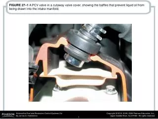
FIGURE 27–1 A PCV valve in a cutaway valve cover, showing the baffles that prevent liquid oil from being drawn into the intake manifold.
FIGURE 27–2 Spring force, crankcase pressure, and intake manifold vacuum work together to regulate the flow rate through the PCV valve.
FIGURE 27–3 Air flows through the PCV valve during idle, cruising, and light-load conditions.
FIGURE 27–4 Air flows through the PCV valve during acceleration and when the engine is under a heavy load.
FIGURE 27–6 Using a gauge that measures vacuum in units of inches of water to test the vacuum at the dipstick tube, being sure that the PCV system is capable of drawing a vacuum on the crankcase (28 in. H2O = 1 PSI, or about 2 in. Hg of vacuum).
FIGURE 27–7 Most PCV valves used on newer vehicles are secured with fasteners, making it more difficult to disconnect and thereby less likely to increase emissions.
FIGURE 27–8 A typical belt-driven AIR pump. Air enters through the revolving fins behind the drive pulley. The fins act as an air filter because dirt is heavier than air, and therefore the dirt is deflected off of the fins at the same time air is being drawn into the pump.
FIGURE 27–9 The external air manifold and exhaust check valve on a restored muscle car engine.
FIGURE 27–10 (a) When the engine is cold and before the oxygen sensor is hot enough to achieve closed loop, the airflow from the air pump is directed to the exhaust manifold(s) through the one-way check valves, which keep the exhaust gases from entering the switching solenoids and the pump itself. (b) When the engine achieves closed loop, the air is directed to the catalytic converter.
FIGURE 27–11 A typical electric motor–driven SAI pump. This unit is on a Chevrolet Corvette and only works when the engine is cold.