Download
1 / 10
100 likes | 234 Views
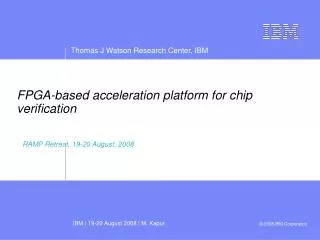
This document presents insights from the RAMP Retreat held on August 19-20, 2008, focused on FPGA-based acceleration in chip verification. Key discussions included architecture optimization for multi-core processors, challenges in software and hardware verification, and methods to improve design efficiency through FPGA-based solutions. The document highlights the importance of flexible FPGA architectures, cycle-accurate modeling, and the need for advanced validation techniques to address verification bottlenecks. Various design methodologies, including component libraries, partitioning flows, and system interconnects, are examined to enhance rapid prototyping and reduce verification cycles.

E N D
FPGA-based acceleration platform for chip verification RAMP Retreat, 19-20 August, 2008
Architecture & FPGA Logic Design, Library models, Validation, Partitioning, Synthesis, Serialization, System Control Firmware, Board Testing Code Sameh Asaad, Mohit Kapur, Chuck Haymes, Daniel Littrell, Ben Parker, Bernard Brezzo, Jose Tierno System packaging, PCB design, layout, mechanical, thermal Todd Takken, Al Lanzetta, Randy Bickford, Shurong Tian, Christopher Surovic, Paul Coteus Host Control Software Ralph Bellofatto, Alda Ohmacht This work is partly sponsored by U. of California Subcontract No. B554331. The prime contractor is LLNL
Architecture (Hybrid Model) Software Development (Architected State) Verification (Cycle-Accurate Model) Power Estimation (Gate- Accurate Model) Introduction • The design of multi-core processors poses many challenges: • Architecture : How do we best organize many cores on a chip, given certain application requirements, power and area constraints etc? How do we architect the memory hierarchy? IO ? • Software Development: Can we get a head start in software development before having hardware brought up in the lab? • Verification: Up to 70% of the hardware design cycle is spent on verification. There is a pressing need to address the verification bottleneck. • Software-based simulators are slow, not keeping up with the increase in processor complexity • FPGA-based simulation acceleration offers a viable alternative to address the above challenges, due to: • Massive parallelism on each FPGA MHz level of simulation performance • Flexible architecture that allows modeling of any digital circuit • Relative ease in constructing large systems of FPGAs and SRAM/DDR memory • Our first target is a cycle-accurate, chip-level verification acceleration of DUT Chip
Motivation for FPGA-based logic verification • Logic verification poses a bottleneck in processor design, accounting for as much as 70% of the design cycle • Software-based verification is too slow and hard to parallelize • Dedicated hardware solutions are too expensive to develop • FPGA-based verification has the best price/performance if we overcome its challenges.
Logic1 Logic2 SER Host SW Ex Control Ex Control FPGA modeling methodology • FPGA-friendly Library of Components • Start by developing a cycle-accurate, FPGA-friendly library of components for custom leaf cells: • Memory (eDRAM) model, using FPGA + external SRAM • Multi-port Register File model, using hyper-clocked Block RAM • Latch/LCB model(s): function only • Component validation through Verity/6th Sense • Chip VHDL should instantiate “wrappers” for these components that enable retargeting to chip and FPGA prototype flows. • Multi-FPGA partitioning Flow: • Build transparent serial communication channels between FPGAs to multiplex N design signal onto M physical traces between FPGAs where N>>M (e.g. 100:1) • Generate wrappers around the partitioned components to connect the virtualized IO signals. One wrapper for each FPGA in the system • Synthesize/place/route each FPGA using normal FPGA flow Logic1 Logic2 User FPGA User FPGA Host Interface Control FPGA
Bill of Materials, … Allegro files for layout Structural Verilog netlist of FPGA system FPGA wrapper file N • FPGA wrapper file 1 • DUT core instance • Serdes instances • Infrastructure instances • Synthesis directives Partitioning Flow Hierachical PCB design description (mainboard.nl, memory.nl, …) Netlister II compiler DUT Top-level netlist (VHDL) Portals Verilog compiler Portals VHDL compiler DADB Mapping file SerDes components Partitioner Infrastructure components • Tool automatically generates top level netlist for each FPGA in the system • Each FPGA is synthesized, placed and routed separately in parallel
FPGA Daughter Card • Xilinx V5 LX330 FPGA (65 nm tech) • Total DDR memory capacity is 4 GB (2GB per DIMM) • Total SRAM memory capacity is 32 MB (4 MB per chip) • 180 LVDS pairs (136 gbps) to backplane through bottom edge connector • 4 Top connectors (2.4 + 2.4 gbps each) can be used for point-to-point links between any two cards in the system • GB Ethernet connection to host • Card can be used stand-alone or in-system Al Lanzetta
Logic Allocation File (1) • (1) Logic Allocation file contains a cross reference from every design latch to the corresponding bit location (frame:offset) in the readback stream • Pre-processing extracts the frames:offsets to be read from the device • After every clock step, software reads the frames of interest into scan file • Post-processing converts the scan file to a waveform viewer file Waveform Generation Process Flow Preprocess to extract frames/offsets of interest Setup File User Logic Control FPGA LX30 iCon Host Control Machine ICAP VIRTEX5 (width=x32) GBE/UDP 32-bit Bus (100MHz) Single-Step & Scan Frames of Interest CAPTURE VIRTEX5 12.5 MHz 100 MHz Scan File Clock Control Macro USER FPGA LX330 Post-Process to create waveform file 400 MHz XTAL Hardware Software