Understanding Bit Counter Behavior in Power Domain Scenarios
This document explores the behavior of a bit counter module under different power domain (PD) conditions. Specifically, it discusses the output state of the bit counter and its data connections when PD1 is turned off. It contrasts scenarios with direct connections versus those using temporary wire assignments, highlighting the implications for signal integrity and logic conditions. The need for clearer definitions and guidelines regarding inferred buffers and pass-through nets is emphasized to enhance design clarity and specification compliance.

Understanding Bit Counter Behavior in Power Domain Scenarios
E N D
Presentation Transcript
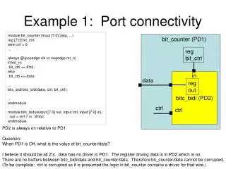
Example 1: Port connectivity module bit_counter (inout [7:0] data, ...) reg [7:0] bit_ctrl; wire ctrl = 0; ... always @(posedge clk or negedge rst_n) if(!rst_n) bit_ctrl <= 8'b0; else bit_ctrl <= data; ... bitc_bidi bitc_bidi(data, ctrl, bit_ctrl); ... endmodule module bitc_bidi(output [7:0] out, input ctrl, input [7:0] in); out = ctrl ? in : 8'hbz; endmodule bit_counter (PD1) reg bit_ctrl in bitc_bidi (PD2) data reg out ctrl ctrl PD2 is always on relative to PD1 Question: When PD1 is Off, what is the value of bit_counter/data? I believe it should be all Z’s. data has no driver in PD1. The register driving data is in PD2 which is on. There are no buffers between bitc_bidi/data and bit_counter/data. Therefore bit_counter/data cannot be corrupted. (To be complete: ctrl is corrupted as it is presumed the logic in bit_counter contains a driver for that wire.)
Example 2: Continuous Assignment module bit_counter (inout [7:0] data, ...) reg [7:0] bit_ctrl; wire [7:0] temp; wire ctrl = 0; ... assign data <= temp; always @(posedge clk or negedge rst_n) if(!rst_n) bit_ctrl <= 8'b0; else bit_ctrl <= data; ... bitc_bidi bitc_bidi(temp, ctrl, bit_ctrl); ... endmodule module bitc_bidi(output [7:0] out, input ctrl, input [7:0] in); out = ctrl ? in : 8'hbz; endmodule bit_counter (PD1) reg bit_ctrl in bitc_bidi (PD2) data temp reg out ctrl ctrl Same scenario as previous slide. Difference is the use of a “temp” wire to connect bitc_bidi/out to bit_counter/data. The continuous assignment statement infers a buffer. So, now what is the value of bit_counter/data when PD1 is shut down? If it is now corrupted, does this really match the specification? Do we really want these 2 situations to have different results with UPF when there wouldn’t be a functional difference otherwise?
Proposed Resolution • Requiring users to specify set_port_attributes or set_pin_related_supply in every situation like that shown in slide 2 is overly burdensome • With no obvious value • Only gain is if the majority of the time, any inferred buffers as in slide 2 are meant to be powered by pass thru domain primary and not driver of net’s primary • Recommend language like the following be added somewhere (not quite sure where, it would probably belong in the create_power_domain command): • “Buffers inferred on a pass-through net are contained within the extent of the domain of the driver of the net and not the domain the net is passing through.” • Need to define the term pass-through net • A pass-through net is a logic net that connects an input port of a domain to an output port of the domain and is not driven nor read by logic in the domain except for the equivalent of buffer logic which serves only to connect the input to the output. • Note that the hierarchical instance structure within the extent of a domain may result in a series of nets and ports that connect the input port of the domain to the output port. The definition of a pass-through net encompasses that complete port/net/port/net/… connectivity path within the domain as though the hierarchy had been flattened to a single port/net/port connection path.