Download

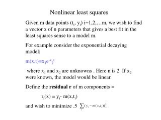
1 / 62
740 likes | 1.14k Views
Discover the principles and applications of Least Squares Adjustment in surveying and geodesy, from statistical analysis to precise measurements. Learn from historical figures and apply modern techniques for accurate results and quality control. Explore functional models and matrix notations for resolving complex surveying measurements. Dive into the intricacies of leveling networks and obtain adjusted observations for enhanced accuracy and reliability.

E N D
INTRODUCING LEAST SQUARES ADJUSTMENT TECHNIQUES FOR SURVEYING AND GEODESY Joel van Cranenbroeck, Managing Director CGEOS CREATIVE GEOSENSING SPRL-S Rue du Tienne de Mont, 11 BE-5530 MONT – Belgium joel@creative-geosensing.com
« One measure is not a measure » • Good practice in surveying leads to perform more measurements than necessary ! Those extra measurements help to provide effective control on the results. • Distance measurements back and forward (traverse network) • Measuring the 3 angles of a triangle ( the sum must be 180 degrees) • Levelling loops (the sum must be zero) • Left and right side telescope measurements (to check the effect of small misalignments of mechanical components of a Total Station into the measurements) • Those “extra” measurements aim to : • Detect outliers in the observations (gross errors) • Check other measurements. • Provide consolidated results (best estimate) • Judge of QUALITY = Precision + Reliability
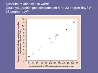
From multiple measurements to an unique result (best linear unbiased estimator) What series has the more “precise” measurement ? How will you consider a new 10th measurement ? What will be your criteria to accept or deny ?
Design, Quality Control and Analysis of Surveying Measurements … • Statistical inference is essential to get a better understanding into the survey measurements. Statistic and Probability are as older as geodesy and surveying. • More and more even, statistical analysis is the only way to provide results such for GNSS where Least Squares Adjustment is playing a fundamental role to achieve high accuracte performances.
True Value, Precision and Accuracy …Frequency distribution of 1 min. GPS data
True Value, Precision and Accuracy …Frequency distribution of 1 hour GPS data
True Value, Precision and Accuracy …Frequency distribution of 12 hours of GPS data
From multiple measurements to an unique result (best linear unbiased estimator) • LEGENDRE invented the Least Squares Adjustment Method for determining the planet’s orbits. • GAUSS provided the mathematical basis and rigorous formulation. • LAPLACE, TCHEBYCHEV et MARKOV contributed with much developments. • The geodesists DOOLITTLE, HELMERT, TIENSTRA, MEISSL et MORITZ performed important work to apply that method in geodesy. • CHOLESKY, BANACHIEWICZ, GAUSS et JORDAN invented algorithms to solve challenges especially in numerical analysis (linear equations).
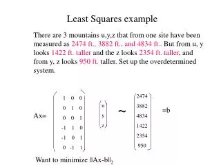
Let’s start with a levelling network • We want to determine the altitude (orthometric height) of B and C knowing the altitude of A and using levelling technique : • HA = 124.180 m. • Observations : dh1 = + 6.14 dh2 = + 8.34 dh3 = - 14.48 dh4 = - 8.35 dh5 = - 6.16
Observation EquationFunctional (Mathematical) Model • We can write for each observation an equation which describe the relationship between the point’s altitude : HA + dh1 = HB HB + dh2 = HC HC + dh3 = HA HC + dh4 = HB HB + dh5 = HA
Observation EquationFunctional (Mathematical) Model • The « unknowns » are written at the left hand side and we introduce the corrections (also named residuals) «vi » : HB = HA + dh1 + v1 HB - HC = -dh2 + v2 HC = HA - dh3 + v3 HC - HB = -dh4 + v4 HB = HA - dh5 + v5
Observation EquationFunctional (Mathematical) Model • In matrix notation, we can write the functional model : Design matrix Observations Residuals/Corrections Unknown/parameters
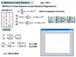
Observation EquationFunctional (Mathematical) Model • We obtain an « over-determined » linear equation system ( n > m ) : • « n » observation equations, here n = 5 • « m » unknowns/parameters ( the orthometric height of B and C ), here m = 2 • To obtain a solution we must impose a « condition » on the corrections. • To minimalise the sum of the squared residuals is the « Least Squares Adjustment Principle » named Minimum Norm L2 … but we can also minimalise the sum of the absolute value of the residuals which is the basis of a « Robust » adjustment based on the Minimum Norm L1 L1 norm L2 norm
Least Squares Adjustment Solution • The solution is obtained by applying the Least Squares principles on the functional model that can be written in matrix notations such : • The squared corrections (Least Squares) is obtained :
Least Squares Adjustment Solution • Let’s start developping :
Least Squares Adjustment Solution • We obtain easily : • And as : • First derivative :
Least Squares Adjustment Solution To « minimise » that result, one need to set the first derivative to zero, then : We get the following solution : Assuming that is positive definite !
Back to the levelling network … • The Normal Matrix N and its inverse :
Back to the levelling network … • The solution is given by :
Adjusted observations and corrections … • The adjusted observations are obtained by : • The corrections by :
The Adjustment’s results for B and C • B = 130.326 m. • C = 138.667 m. • A = 124.180 m. • Corrections : v1 = + 0.006 v2 = + 0.001 v3 = - 0.007 v4 = + 0.009 v5 = + 0.014
The Stochastical Model … • The idea is to integrate the information about the accuracy of the measurements - a priori. • One can speak about an entire definite stochastical model by the standard deviation of the observations estimated a priori. • That means we have to take into account all the factors … and not only the manufacturer specification ! • For a Hz direction for instance : • The standard deviation of the Hz measurement • The centrering error of the instrument • The centrering error of the target • etc. • The variance-covariance matrix of the observations is built with all that information …
The Stochastical Model … • That matrix is defined by the cofactor matrix and the variance factor. That is the variance factor of the weight unit …
The Stochastical Model … • The inverse matrix of the variance-covariance matrix is named « weight matrix ». • The function to minimize becomes : • With the solution :
The « a posteriori » qualityindicators are defined … • Those are the variance-covraiance matrices scaled by the variance factor « a posteriori ». • Variance factor : • variance-covariance matrix of the parameters : • variance-covariance matrix of the adjusted observations : • Matrice variance-covariance des corrections :
Back to the levelling network … • Estimation of the variance factor « a posteriori » often named empirical variance factor : • Remember we selected the a priori variance factor to 1 cm !
Back to the levelling network … • Variance-covariance matrix of the parameters : • The standard deviation of the parameters are :
Quality of the results … still some questions … Now we have all the information that is needed to « judge » of the quality results … What if we had choosen another point then A ? Is it necessary to fix a point ?
Back to the levelling network … • Variance-covariance matrix of the observations :
Back to the levelling network … • Variance-covariance matrix of the observations :
Back to the levelling network … • Variance-covariance matrix of the corrections :
Redundancy, degree of freedom … • The degree of freedom « r » isdefined as the differencebetween the number of observation and the number of parameter : • The trace of the matrix isegal to the degree of freedom « r » :
Redundancy, degree of freedom … • Each diagonal element of that matrix is expressing an important information about how each observation is contributing the the total redundancy of the system … • We consider the following criteria : not controlled observation badly controlled observation controlled observation well controlled observation
Back to the levelling network … • Local redundancy factor « r » : r1 = 0.625 r2 = 0.625 r3 = 0.500 r4 = 0.625 r5 = 0.625 • We have pretty well controlled observations …
From a Levelling Network up to GPS Network …The functional models are similar … • A = R + b1 • B = R + b2 • C = R + b3 • D = R + b4 • B - F = b5 • C – F = b6 • D - F = b7 • E - F = b8 • A - D = b9 • B - D = b10 • C - D = b11 • E - D = b12 R b1 A b2 b3 B b4 b10 b9 b11 C D b5 b6 b7 b12 F E b8
From a Levelling Network up to GPS Network …The functional models are similar … R b1 A b2 B b3 b4 b10 b9 b11 C D b5 b6 b7 b12 F E b8
How to model a simple Levelling line ? Setup the equations for each observation Build the functional model and derive the Least Squares Adjustment solution without considering any observation (simulation). What would be the “reliability” ? R D1 A B C D2 D3 D4 D D5 E F D6
How to model a simple Levelling line ? Setup the equations for each observation Build the functional model and derive the Least Squares Adjustment solution without considering any observation (simulation). What would be the “reliability” ? R D1 A B C D2 D3 D4 D D5 E F D6
In geodesy and surveying we have also directions ( Hz , Vz ) and distances … • Like for the levelling network we have to write the “functions” to setup the equations … • But the Least Squares Adjustment method is dealing with linear equations (non linear Least Squares is dealing with non linear functions but it’s out of our scope) • So with have to “linearized” the functions we are using by applying a decomposition in series of Taylor limited to the first order (because that’s the linear part…) around an approximated value.
Gl0 l0 Direction HZ : B lAB A
Least Squares Adjustment We find exactly the same adjusted coordinates than with Leica GeoMoS !
How about a Traverse ? S R A B C F