Download
1 / 23
230 likes | 265 Views
This article discusses the Mucool LH2 Absorber Program in 2006, including recent history and accomplishments, window measurements using different methods, and the next steps for window certification and manufacturer selection.

E N D
LH2 Absorber Status n n n n n n n n nnn Mary Anne Cummings NFMCC UCLA January 31, 2007 Muons, Inc. Jan 31, 2007
Absorber program 2006 • In the past year – • Re-instrumented KEK absorber for next MTA LH2 test • Established a new (and practical method) of window measurement • Completed GH2 RF test in MTA solenoid (most interesting experimental result out of NFMCC) • Overall, Mucool • Has a dedicated test area with a planned ~ 550W refrigeration capacity, designed for LH2 • Has new FNAL LH2 cryogenic expertise • Has an established LH2 safety committee with an critical, but encouraging, attitude toward its goals • Has an established LH2 track record what program? Jan 31, 2007
Mucool MTA Absorber Task List Current program: • GH2 RF tests with magnet* Done! • KEK LH2 test (convection) 2nd test in ‘07 • FF LH2 absorber construction and tests ??? • FF LH2 and RF first cooling cell test ??? • GH2 beam test* Still scheduled • Cooling cell beam tests ??? Future projects: • LH2 HCC cryostat (Muons, Inc.) • Lithium Hydride • Other + Window tests… * Muons, Inc. Jan 31, 2007
LH2 recent history • 2004: • 1.5 FT scientists, 1 FT engineer (E. Black), 1 PT engineer (M. Haney), 1 PT graduate student, undergraduates • NIU machine shop, electronics shop, UIUC computer, U Miss shop • FNAL cryo group, metrology group • Japan-USA funding (KEK MTA convection absorber) • 2005: (after ICAR $$ disappeared) • 1 scientist PT • FNAL cryo group, vaporization lab, beams group • P8 lab • 2006: • 1 scientist PT • FNAL cryogroup, metrology group, vaporization lab, beams group • Lab 6 (K. Kephardt) • 2007: • 1 scientist <PT • FNAL SciDet support, beams group • Lab 6 Jan 31, 2007
Window measurements Photogrammetry ~1000 points Strain gages ~ 20 “points” Old CMM ~ 30 “points” We have tried: chemical – mechanical - optical methods And now – sonic! New CMM ~ 100s “points” Jan 31, 2007
“Feather” probe CMM • Apollo Research Model 1022 CMM Touch Probe System • high frequency resonating stylus to detect contact with object • <10 mg force applied (700g old test) • contact detected by change in resonance • insensitive to CMM movement • ~ few micron sensitivity At FNAL SciDet facility Large clearance for test setup Jan 31, 2007
Photogrammetic Test Setup (FNAL) Beautiful, detailed, but maybe overkill Optical coating (another complication) Pressurization measurement with photogrammetry Shape measurement with photogrammetry Jan 31, 2007
Window measurements New CMM data points Old CMM data points • Initial measurements: • calibration ball measured ~ 2 microns consistency • 1st measurements of window profile – self-consistent, but did not match design thickness! (220 vs. 126m - will investigate) • correction needed (but understood) for finite probe radius – least errors at center (thinnest part) • online computation New Personnel: Mike Roman (FNAL) Mike Wojcik Jan 31, 2007
FNAL Design Requirements: • Vacuum • Burst test 5 vacuum windows at room temp. to demonstrate a burst pressure of at least 75 psid for all samples. (pressure exerted on interior side of vacuum volume). • Non-destructive tests at room temperature: • External pressure to 25 psid to demonstrate no failures: no creeping, yielding, elastic collapse/buckling or rupture • Other absorber vacuum jacket testing to ensure its integrity • Absorber • Room temp test: pressurize to burst ~ 4 X MAWP (25 psi at FNAL) • Cryo test: a) pressure to below elastic limit to confirm consistency with FEA results b) pressure to burst (cryo temp – LN2) ~ 5 X MAWP fromASME: UG 101 II.C.3.b.(i) FNAL Safety requirements Jan 31, 2007
RAL Window Safety Requirements • Mucool manufacture and measuring procedures deemed safe • RAL window pressure test requirements (Absorber and Vacuum) Test Pressure Test temperature # of tests required Remarks Test to rupture. Windows to subject to thermal cycling before the test 96 psi(4 x Design P) 3 @ 293K Test to rupture. If shrapnel is evident, one further test will be needed. The additional test will have the safety mesh fitted to verify that shrapnel doesn’t reach the safety window. 1 or 2 @ 77K > 96 psi(5 X Design P) Room temp Test for buckling (external) 25 psi 1 **Design Pressure = 24 psid MAWP FNAL = 25 psid - Effectively, the same for MICE and MuCool Jan 31, 2007
Next steps.. • Window certification • Have a practical and sufficient measurement technology • Design certification different for vacuum/absorber windows, and not yet completed for “inflected” window need this be done for only one diameter? • Tentative real window certification: • Materials inspection • Measurement • Sub-elastic limit pressure tests (on CMM?) • Next Manufacturer? • U Miss. • Review with Safety committee Jan 31, 2007
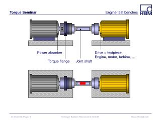
KEK test cryostat at MTA/FNAL Pre-cryo plant:: cooling power from He dewars LH2 controls system in place Jan 31, 2007
Convection Absorber • Convection is driven by beam power and internal heaters • GHe heat exchanger removes heat from absorber walls • Flow essentially transverse • Self-regulating • Simpler system, less LH2 • Prototype exists.. FF Jan 31, 2007
Absorber physics issues 1. Heat absorption Benchmark for heat deposition for MC and NF (m+m- Collider feasibility study and NFII) in LH2 [3.24*1013m/s] 4*1012 (~1013) m's/bunch * 15/s * 4.7MeVg-1cm2 * 0.0708g/cm3 * 1.6*10-13J/MeV = *[1.4 HCC/straight] 3.2 (~8)[2.4] W(J/s)/ cm pathlength [] = LEMC starting point, 3 TeV 2. Density uniformity how large a temperature gradient is tolerable? Convection absorbers push the limits of large heat deposition into relatively small volumes of LH2 – knowledge will help determine absorber design. Jan 31, 2007
Convection theory and data.. Comparison of 1st KEK MTA LH2 test to CFD calcs (K. Cassel et al, 2004, IIT): DT = 2.4K for 22W (~147 W/m) deposition in KEK absorber Required heat absorption for previous cooling channel: ~800 W/m but a possibility for LEMC? Jan 31, 2007
Temp. gradient on performance Absorber • Exaggerate and simplify temperature gradient by replacing uniform absorber with 2 different density halves (14% higher/lower diff) but same average density and compare with uniform density absorber • < 1% change in momentum and space distributions (average and sigmas) • “Large” temp gradient may be tolerated if it is stable G4 Beamline simulation of four cooling cells Jan 31, 2007
KEK upgrades Electric heater installed Electric heater Temp sensors CX-1050-SD L-H2/LHe Level sensor in absorber Jan 31, 2007
2007 MTA KEK LH2 Absorber tests • February 2006 upgraded instrumentation • January 2007 installed heater • Preliminary safety review approved • Preliminary safety check list completed • Schedule for 2007 MTA LH2 test to be determined Jan 31, 2007
MTA Beam Beamline designed and costed by C. Johnstone for the MTA. Part of the Linac Instrumentation Test Program New magnets now in production MTA stable beam In 2007 Budget Linac beam Jan 31, 2007
Lithium hydride • LiH reacts violently with water, so water cooling must be carefully designed and implemented (it’s not certain it can be done safely). Halon fire suppression is probably required. • Handling of prefabricated LiH is not terribly hazardous (gloves and dust masks); fabrication (casting) will require QC, should be left to experts. • Bare LiH can be pumped down to vacuum; it is best to repressurize with dry Nitrogen, but room air is OK. • LiH cannot be in direct contact with aluminum (Al migrates). • Thermally-induced stresses could be a problem for high rate beams • Surface oxidation from air moisture is almost inevitable; how will it affect the cooling performance? • LiH is a hazardous material; the safety issues are very different from those of liquid Hydrogen, but comparable in difficulty. Substantially less hazardous substantially less safety work! Jan 31, 2007
If it were up to me… • Window measurement will proceed with the new CMM system and probes • The KEK LH2 absorber test will be completed by this spring • The first “cooling cell” component test will be the GH2 RF cavity inside the MTA solenoid in the MTA beam – and make this a priority • Put the KEK LH2 absorber in the MTA beam IF everything, including 6D MANX, “slides” indefinitely • Build a “one turn” HCC prototype and fill it with H2 (why not?) • Any other possible cooling component that exists we should consider testing at MTA These are administrative issues.. Jan 31, 2007
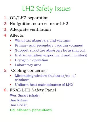
Safety • For H2, two principles driving system design : • O2 and H2 separation • No ignition sources • At FNAL: guidelines for the LH2 absorber system • America Society of Mechanical Engineers (pressure and vacuum vessels, etc.) • National Electrical Code <= (Class I Division II, or “instrinsically safe”) • Compressed Gas Associates • Fermilab Environment Safety and Health Code • Ignition sources – electrical, friction, impact, auto-ignition • Minimum energy for ignition of H2 is 0.017 mJ at 1 atm. • Combustion H2 /air ratio from 4% to 75% PRIMARY SAFETY MECHANISM IS CONTAINMENT: “EXCEPTIONS HANDLED BY VENTING LH2 OUT OF THE AREA Jan 31, 2007