LH2 Absorber R & D
220 likes | 414 Views
LH2 Absorber R & D. Illinois Consortium for Accelerator Research (IIT, NIU, UC, UIUC), U Miss Oxford U. Mary Anne Cummings NIU. Mucool LH2 Absorber Collaboration . E. L. Black, M. Boghosian, K. Cassel D. M. Kaplan, W. Luebke, Y. Torun Illinois Institute of Technology

LH2 Absorber R & D
E N D
Presentation Transcript
LH2 Absorber R & D Illinois Consortium for Accelerator Research (IIT, NIU, UC, UIUC), U Miss Oxford U Mary Anne Cummings NIU Mucool FNAL
Mucool LH2 Absorber Collaboration E. L. Black, M. Boghosian, K. Cassel D. M. Kaplan, W. Luebke, Y. Torun Illinois Institute of Technology S. Ishimoto, K. Yoshimura KEK M. A. Cummings, A. Dyshkant, D. Hedin, D. Kubik Northern Illinois University D. Errede, M. Haney University of Illinois, Urbana-Champaign M. Reep, D. Summers University of Mississippi Y. Kuno Osaka University G. Barr, W. Lau Oxford University C. Darve, C. Johnstone*, A. Klebaner, B. Norris, M. Popovic, S. Geer FNAL * also research faculty at IIT Mucool FNAL
r r R Absorber Window Design Modified Torispherical integrated window and flange design (tapered detail at left). Machine parameters shown. Precision measurement of window and flange with CMM at FNAL Industrial Center. Mucool FNAL
Window manufacture (U of Miss) Flange/window unit machined from aluminum piece Backplane for window pressure tests Mucool FNAL
Window Test Setup Test setup at NIU for window , front view: pressure control system Backplane with connections, and with window attached Strain gages applied to window Mucool FNAL
Photogrammetry • Non-contact measurement of strain by calculating displacement • Compare with strain gage readout and FEA calculations FEA calc. for displacement Mucool FNAL
Photogrammetry measurements during earlier pressure test. Note the projected dots! Mucool FNAL
Latest window burst test Mucool FNAL
Rupture tests 1. 130 m window The Latest: 340 m window 3. Leaking appeared at 31 psi ..outright rupture at 44 psi! 2. 350 m window Burst at > 120 psi Burst at ~ 120 psi Burst at ~ 120 psi Mucool FNAL
Deformation of Window end-cap Vs test pressure 0.6 0.5 0.4 0.3 P=.18MPa Test pressure (MPa) 0.2 0.1 0 0 20 40 60 80 100 120 140 160 distance from end-cap centre line (mm) FEA results by Oxford Comparison of results on 130m window 1 at 0.18 Mpa test pressure: FEA, elastic region only FEA, non-elastic region included NIU Photogrammetry results & non-linear FEA calculation Mucool FNAL
Comparison of results on 130m window at 0.24 Mpa test pressure Comparing the Oxford and linear FEA results with the NIU photogrammetry data FEA, non-elastic region included Mucool FNAL
FEA Calculations • 350 micron window (W. Lau) • Non-elastic region included • Three dimensional analysis, necessary for vibrational analysis Stress distribution when first yield developed at 77.7psi (0.536 MPa)pressure Mucool FNAL
Flow Tests Density maintenance: • Nozzle design and arrangement (E.Black, S. Dyshkant) • Bates LH2 target heat carrying performance determined by total eN cross section measurements. We’ll need other confirmation. • 3-dim LH2 absorber flow simulations (W. Lau) • Will run 3-d sims for water, air, LH2 – demonstrate for water with the “analog” simulation at NIU • Absorber instrumentation • Absorber integrated into a cryo system, with extreme temperature and pressure variations considered for safety. • Heat loss/feedthrough Mucool FNAL
Results of the fluid flow analysis:- Oblique nozzle arrangement with air flow at room temperature Air inlet Inlet velocity = 100 m/s Velocity profile in Y-direction Mucool FNAL
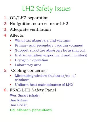
Safety Mu-Cool Safety Panel has been formed. It consists of: Wes Smart (Chairman) Jim Kilmer Jim Priest Safety guidelines 1. Results of FEA calculations which show that the maximum window stress at 25 psid internal pressure is less than (0.25)x(ultimate strength). 2. Results of a cold pressure test per paragraph II.C.3.b.(i) (for metal flasks) of the LH2 Target Guidelines. I would suggest that at least one window be burst under cold conditions. Burst test at NIU with nitrogen 3. Results of a room temperature pressure test per paragraph II.C.3.b.(ii) of the LH2 Target Guidelines. Burst test 4. Copy of the Material Certification Sheet of the material from which the windows are fabricated provided 5. Other; including results of tensile testing samples of the material. Mucool FNAL
Design of LINAC LH2 Absorber Beam Test Mucool FNAL
Next Burst test with nitrogen at NIU Feb ‘02 1st safety report to committee Mar ‘02 Flow tests/ 3-d FEA study Apr ’02 Heat exchange/containment for LH2 cryostat May ‘02 Instrumentation Jun ’02 - ?? LH2 safety LH2 monitoring LH2 physics 11 cm radius absorber Jun ’02 - Data acquisition LH2 Beam Cryotests for convection at NIU Jul ’02 - ?? The program gets redefined after every milestone! Mucool FNAL
s D r R r displacement displacement r L R r beam axis beam axis Thin Window Design Minimize window thickness: Variable thickness near window edges can further reduce the minimum window thickness near beam: Hemispherical: t = 0.5PL / (SE - 0.1P) s = 0.5D Ellipsoidal: t = 0.5PD / ( SE - 0.1P) s = .25D Torispherical: t = 0.885PD / ( SE - 0.1P) s = .169D t = min. thicknesss = sagitta Minimum thickness depends on shape (ASME Standard) ANSYS Finite Element Analysis, Zhizing Tang, FNAL. Mucool FNAL
Strain Gage Measurement • Measure the strain on window with strain gages • Use Finite Element Analysis program (ANSYS) to relate vessel pressure to maximum window strain – confirm this with strain gages applied to window surface FEA mesh for calcs. on the window-flange unit < two different gages Instrumented window Mucool FNAL
Strain gage data 350m window Strain vs. time – the gage ceases to return to resting position after ~ 80 psi; demonstrating the yield point. Rosette Gage at 12 mm yielding.. Mucool FNAL
Forced-Flow Absorber Design External Heat Exchange: Mucool ~ 100W (E. Black, IIT) Large and variable beam width => large scale turbulence Establish transverse turbulent flow with nozzles – complicated, hard to simulate Mucool FNAL
Convection absorber design Internal heat exchange: Convection cell is driven by heater and particle beam. Heat exchange via helium tubes near absorber wall. Flow is intrinsically transverse. Output from 2-dim Computational Fluid Dynamics (CFD) calcs. illustrate the concept. (K. Cassel, IIT) Lines indicate greatest flow near beam center. < Studies are encouraging, but there is a poorly known parameter: hLH2, coefficient of convective heat transfer. Prototyping of this design is being done by Shigeru Ishimoto et al at KEK. Mucool FNAL