Download
1 / 8
90 likes | 224 Views
Learn about power processing, converter topologies, electrical specifications, input/output parameters, safety design, and thermal management in power electronics modules. Enhance your knowledge with Celestica's expert insights.

E N D
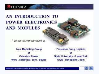
AN INTRODUCTION TO POWER ELECTRONICSAND MODULES A collaborative presentation by Your Marketing Group at Celestica Power www . celestica . com / power Professor Doug Hopkins at State University of New York www . dchopkins . com
Welcome and Outline An Introduction to Power Electronics and Modules An Introduction to The System • Power Processing • Power Processing - Conversion • Power Processing - Supply • Power Processing - Linear or Switch-mode • Background in Converter Topologies • Defining Electrical Specifications • Knowing Your Input Specifications • Input Filtering • Transient Suppression • Knowing Your Output Specifications • Standards, Certificates & Regulations • Design for Safety • Not Just Electrical Design • Thermal Issues • Safe Operating Area • The Module as a Component Welcome, Celestica is a world leader in designing power supply solutions to address your needs. However, the more our customers understand our capabilities, the better we can fully meet those needs, now and in the future. For those of you who are new to specifying power supplies or need a better understanding of power electronics, we offer the following presentation. Visit this page often as we add more topics. If you have special interests in a particular topic, please contact us at Celestica.
Direct board mount or integral modules • 30A high-efficiency, high-transient isolated power supply • Isolated power supply for high-end micro-processor
Board-Mount Power Celestica offers highly dense power for board mount applications.
Iin Iout Vin Power Supply Vout Knowing Your Input Specifications Defining Electrical Input Specifications SPECIFICATIONS Electrical Power Input Vdc Input Vac Input • Vin-rms range • Iin-rms range • Efficiency • Sags, surges and transients • Hold-up time • Power factor • In-rush current • Noise and THD • Vin range • Iin range • Efficiency • Ripple current • Switching noise • Surge/Start-up current
DC Input Specification - Vin • Typical DC sources: • Car Battery - typical 12 volts with 11 to 14 volts variation • Solar Cell - 0.5 to 1 volt per cell depending on sunlight • Telecom Bus - nominal 48 volts with 36 to 72 volts variation • PC internal - 5 volts, +/- 10% • Example: A Telecom bus has a Vin operating range of 36 to 72 volts. • If the input voltage drops below 36V, a supply will typically shut down. • If the input voltage exceeds 72V, a power supply may be damaged by the excessive high voltage. • A supply can be designed so it can handle short durations of high input voltage, such as line transients due to lightning or surges. • For example, a supply may have a surge rating of 100V for 100usec. Specifying Vin defines the source voltage operating range.
DC Input Specification - Iin, Pout, • Pout (output power) = Vout x Iout • (efficiency of the PS) = Pout / (Vin x Iin) • Typically between 0.5 to 0.98 • Substituting and solving for Iin Iin = (Vout x Iout) / (Vin x ) Iin is the current drawn by the power supply (PS) and derived by Note: Worst case Iin occurs at lowest value of Vin, e.g. for telecom, the most current is at Vin = 36 V.
Irip Iin Time DC Input Specification - Irip Irip is • specified as peak-to-peak • occurs at usually < 10Mhz • typically, < 10% of max Iin • For example, if Iin max is 10A, Irip p-p should be less than 1A Iin has a ripple current, Irip, due to internal power switching.