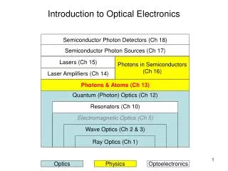
Introduction to Electronics
Introduction to Electronics. Electronics Unit, Lecture 3. Prototyping Techniques and Soldering Electronics Unit – Lecture 3. Schematic Diagrams Assembly Methods Soldering Tutorial. Schematic Diagrams. Schematic diagrams represent an electronic circuit in symbolic form.


Introduction to Electronics
E N D
Presentation Transcript
Introduction to Electronics Electronics Unit, Lecture 3 Electronics 3
Prototyping Techniques and SolderingElectronics Unit – Lecture 3 Schematic Diagrams Assembly Methods Soldering Tutorial Electronics 3
Schematic Diagrams Schematic diagrams represent an electronic circuit in symbolic form. A schematic need not depict the actual physical arrangement of the components Electronics 3
SkeeterSat Schematic Electronics 3
Component Symbols Wires and wire connections Current practice: Either A or B is acceptable C is the preferred style D is seldom used E is interpreted as a non-connection Electronics 3
Component Symbols Power sources (V) and common connections (GND) Electronics 3
Component Symbols Resistors (R) and Capacitors (C) Electronics 3
Component Symbols simple inductors Inductors (L) and Transformers (T) adjustable adjustable tapped The two parallel lines indicate that the inductor is wound on a core of iron, iron powder, or ferrite material. transformers Electronics 3
Component Symbols Diodes (D) The arrow points in the allowed direction of conventional (positive charges) current flow. The bar represents the cathode, marked with a band on most parts. Electronics 3
P-channel junction field-effect transistor bipolar PNP junction transistor bipolar NPN junction transistor N-channel junction field-effect transistor P-channel MOS field-effect transistor Component Symbols Transistors (Q) N-channel MOS field-effect transistor Electronics 3
Component Symbols Integrated circuits (U) Most complex integrated circuits are represented on schematic diagrams as a rectangular block symbol, with pin numbers and, usually, pin functions indicated; but many logic integrated circuits have special symbols that identify their function. Electronics 3
Component Symbols double pole single throw DPST single pole single throw SPST Switches (S) and Relays (K) single pole double throw SPDT double pole double throw DPDT single pole double throw relay rotary switch 1 pole, 5 position Electronics 3
Component Symbols Miscellaneous Components and Devices Electronics 3
Drawing Schematic Diagrams Use one of the many schematic capture programs available on the WWW for free download, for example: ExpressPCBhttp://www.expresspcb.com/ EagleLitehttp://www.cadsoftusa.com/freeware.htm These usually include printed circuit board layout capability as well. The SkeeterSat schematic shown earlier was prepared with ExpressPCB Electronics 3
Building a prototype Solderless breadboards Perfboards or Protoboards Manhattan Construction Dead Bug Construction Etched Circuit Boards Electronics 3
Solderless Breadboards The term breadboard originated in the early days of radio, when many experimenters actually built circuits on the wooden boards used in their mother’s kitchen for rolling out bread dough. modern solderless breadboards Best thing to come along since sliced bread! A ham radio transmitter circa 1930 Electronics 3
Perfbord or Protoboard Components are soldered to the board, with connections made using a combination of short pieces of wire and the copper traces already present on some versions of these boards. Electronics 3
Manhattan and Dead Bug Construction Electronics 3
Etched Circuit Boards Electronics 3
Soldering Tutorial Soldering – fastening metal objects using molten metal (solder) as the glue. Three requirements Low melting point metal (wire solder) Heat source (soldering iron) Flux (to prevent surfaces from oxidizing) Electronics 3
Types of Solder Tin-Lead solders 60% Tin, 40% Lead - solid at 361° F, liquid at 374° F 63% Tin, 37% Lead - eutectic point is 361° F no “pasty” range so joint movement less a problem Silver-bearing Solder 62% Tin, 36% Lead, 2 % Silver - solid at 354 ° F, liquid at 372 F often used for surface mount components whose contacts contain trace amounts of silver Electronics 3
Soldering Irons Constant wattage Iron is continuously “ON” and eventually reaches equilibrium temperature 20 to 25 watt iron sufficient for circuit board assembly Constant temperature Tip incorporates a thermostatic element to maintain desired tip temperature 650 – 750 ° F appropriate for circuit board assembly But wait…..even better… Weller® 30 watt iron Electronics 3
Soldering Irons Feedback control maintains tip at desired temperature Adjustable, often with analog or digital temperature display Many have grounded tip to help prevent ESD damage Temperature Controlled Solder Station Weller® solder station Electronics 3
Types of Flux Rosin Flux Type R – ordinary rosin – most common Type RMA – mildly activated rosin Type RA – activated rosin – use with care Acid Flux – NEVER, EVER use this for electronics Electronics 3
Flux-core solder Most solder used for electronics assembly is in wire form, with the flux incorporated inside the solder. Multi-core solder has several (usually five) separate flux channels within the solder. For circuit board assembly use wire solder with a diameter of about 0.025 inch or less Electronics 3
Soldering a Component Use a lead bending jig, if available, to form the component leads to the correct spacing If a bending jig is not on hand, grasp the leads, not the body, of the component with needle-nosed pliers and bend gently. Electronics 3
Insert the component’s leads through the holes in the circuit board. The body should lie flat against the board without having to force it down. Soldering a Component Turn the board over and gently bend the component leads outward to hold the component in place Electronics 3
Clean the iron tip by wiping on a damp sponge. Tin the tip by applying solder, then wipe again. Soldering a Component QT Movie Clip Apply the iron in contact with both the circuit board pad and the component lead. Apply solder to the joint, not to the iron, and allow the heated joint to melt the solder QT Movie Clip Electronics 3
Use a pair of flush-cutting wire cutters to cut off the excess lead length as close to the board as possible. Hold the lead so will not fly away when cut, a possible occasion for eye injury. !! WEAR SAFETY GLASSES !! Soldering a Component QT Movie Clip Good soldering Inspect the soldered and trimmed lead. It should be uniform and shiny, with no cracks, gaps, or graininess. Bad soldering Electronics 3
Activities E3a. Use the supplied assortment of components and practice soldering them to the perfboard. E3b. Locate each SkeeterSat component on the schematic diagram, and then on the circuit board layout. Be careful to note if the part has to be oriented in a special way. You will actually construct your SkeeterSat in the next session. Electronics 3