Download
1 / 16
160 likes | 179 Views
This is an outline of the LGAD RD50 projects at CNM, including gallium implantation, N-rich silicon strip sensors, measurement of doping profile, investigation of thin LGAD properties, and acceptor removal in boron-doped silicon. The aim is to enhance the radiation hardness of LGAD detectors.

E N D
Outline • Gallium Implantation to Enhance the Radiation Hardness of LGAD DetectorsCarbon doping. • Strip sensors made of N-rich Silicon (See A. Dierlamm´s Talk). • Measurement of the Doping Profile in Low-Gain Avalanche Detectors (see H. Sadrozinski´s talk). • Investigation of the properties of thin LGAD(See M. Carulla´s talk and N. Cartiglia´stalk). • Investigation of acceptor removal in boron doped silicon wafers and LGAD. To be submitted.
Rd50 funded project The aim of this RD50 Common Project is to enhance the radiation hardness of Low-Gain Avalanche Detectors (LGAD) . Dopants such as Ga or Al form complexes with radiation-induced defects, which may have less impact on device performance, when compared to the boron related defect (Bi-Oi) complex.
Reference Ref: A. Khan et al., “Strategies for improving radiation tolerance of Si space solar cells”, Solar Energy Materials & Solar Cells 75 (2003) 271–276. RC = 0.04 cm-1 for Ga RC= 0.08 cm-1 for Al RC= 0.15 cm-1 for B
GEANT4 Pn diodes without multiplication! Gallium has lower penetration than Boron, but higher diffusion (with annealing)
IV Boron
Conclusion and futurework do be done (Ga) • Wafers are being diced in these days. They should be ready by next Friday. We should discuss distribution of samples. • Detectors work well as standard boron doped pn diodes. • 4-point probe technique to measure Ga doping concentration (before and after irr.) • SIMS measurements to extrapolate doping profiles. • Calibration of simulation model for Ga implantation. • Irradiation of diodes with neutron and proton (electrons ?)to calculate removal constant to be compared to Boron doped devices.
Investigation of acceptor removal in boron doped silicon wafers and LGAD • We want to use two different technological approaches. • Diffusion of C in silicon wafer (bare wafers and n-p diodes) • Implantation of C in the multiplication junction.
The main idea is that carbon co-doping can reduce the concentration of B-O defects, as a result of the formation of more energetically favorable carbon-oxygen (C-O) complexes. Plan for Acceptor Removal study E. Donegani, Comparison between n-type and p-type sensors,RD50 meeting, 01.12.2015 CERN. RD48- 3rd status report 31-12-1999
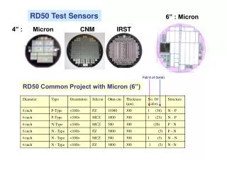
Wafer selections at CNM Note: FZ and CZ wafers have different initial C and O concentrations.
Fabrication plan • We will use 4x6 wafers with different resistivities (total 28 wafers). • 2x6 wafers will be “doped” in chlorine (DCE dichloroethane) gas to diffuse C into the bulk [1]. Expected concentration of [O] and [C] after diffusion. [1] L. Fonseca et al., Silicon wafer oxygenation from SiO2 layers for radiation hard detectors, Microelectronics Reliability 40 (2000) 791-794.
RUN CARBON DOPING The electrically active impurity concentration can be calculated from the measured resistivity value ρ by The doping concentration can be measured by the 4-point probe technique available at CNM. We plan to measure ρ before and after irradiation in the wafers with and without C. The wafers will be diced in 1cm2 samples and sent for irradiation with neutrons. After that, they will be measured again by the 4-point probe technique to measure the change in ρ . • R. Wunstorfet al., Investigations of donor and acceptor removal and long term annealing in silicon with different boron/phosphorus ratios, NIM A A 377 (1996) 228-233. • YichaoWu et al., Suppression of boron-oxygen defects in Czochralski silicon by carbon co-doping, Applied Physics Letters 106, 102105 (2015); doi: 10.1063/1.4914889
Diodes • The remaining 2x6 wafers (1 set of wafers doped with C) will be processed to make standard n-p diodes. • This will be an alternative method to measure Neff before and after irradiation with CV plots. • For the high doped wafers the method may be difficult due to the low electrical breakdown expected in the diodes (See simulation below). Bulk doping Simulation Mask cnm_629
Implantation of C in LGAD • The last process that we want to explore at CNM is to enrich with C atoms only the multiplication layer of the LGAD devices. This could be achieved by implanting C only in the first 5-6 um of the wafer surface. • Standard mask used in the past for LGAD devices. • An optimization with simulation software tools like Silvaco and Sentaurus is necessary before starting the process. Carbon’s high efficiency in trapping silicon self-interstitials can cause the reduction of boron diffusion in C-rich silicon samples and this can lead to a change in the multiplication layer of LGAD sensors during the fabrication process.