Download
1 / 63
630 likes | 656 Views
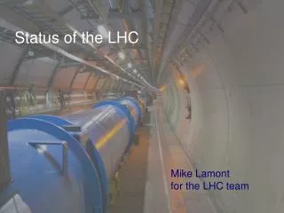
The status of the lhc and future projects at cern. Emmanuel Tsesmelis Directorate Office, CERN & Visiting Lecturer, JAI The University of Oxford 13 March 2009. Table of Contents. Status of the LHC The LHC Accelerator Commissioning with Beam Sector 3-4 Incident

E N D
The status of the lhc and future projects at cern Emmanuel Tsesmelis Directorate Office, CERN & Visiting Lecturer, JAI The University of Oxford 13 March 2009
Table of Contents • Status of the LHC • The LHC Accelerator • Commissioning with Beam • Sector 3-4 Incident • Commissioning the Physics Programme • Physics Run 2009-2010 • Future Projects at CERN • ATLAS/CMS Interaction Regions • LHC Pre-Accelerators
LHC Accelerator & Experiments CMS/TOTEM LHCb ATLAS/LHCf ALICE
LHC LAY-OUT • The LHC is a two-ring superconducting proton-proton collider made of eight 3.3 km long arcs separated by 528 m Long Straight Sections. • While the 8 eight arcs are nearly identical, the 4 straight sections are very different.
High beam energy in LEP tunnel superconducting NbTi magnets at 1.9 K Momentum at collision 7 TeV/c Momentum at injection450 GeV/c Dipole field at 7 TeV 8.33 Tesla Circumference 26658 m Stored energy magnets 9.4 GJ High luminosity at 7 TeVvery high energy stored in the beam 25 ns bunch-spacing Beam power concentrated in small area Luminosity 1034 cm-2s-1 Number of bunches 2808 Particles per bunch 1.1 1011 DC beam current 0.56 A Stored energy per beam 360 MJ Normalised emittance 3.75 µm Beam size at IP / 7 TeV 15.9 µm Beam size in arcs (rms) 300 µm Limited investment small aperture for beams Arcs: Counter-rotating proton beams in two-in-one magnets Magnet coil inner diameter 56 mm Distance between beams 194 mm
LHC Main Bending Cryodipole 8.33 T nominal field 11850 A nominal current
Magnet Interconnections Consist of several operations: • TIG welding of cryogenic channels (~50 000 welds) • Induction soldering of main superconducting cables (~ 10 000 joints) • Ultrasonic welding of auxiliary superconducting cables (~ 20 000 welds) • Mechanical assembly of various elements • Installation multi-layer insulation (~ 200 000 m2) DIPOLE-DIPOLE INTERCONNECT BEFORE FINAL CLOSURE All interconnections completed in November 2007
Preparing the LHC Synchronisation Tests TT40 – Sept/Oct 2003 TI8 – Sept 2004 TI2 - 2007
Synchronisation of LHC Clockwise Beam 8-10 August 2008 The yellow spot shows a bunch of a few particles arriving at Point 3 of the LHC ring
Injected Beam to LHCb 22-24 August 2008
3rdSynchronisation Test 6-7 September 2008 CMS Calorimeter and Muon System Recording Beam Dump on TCT in 5L
10 September 2008 • 10:26 hrs Beam 1 (clock-wise beam) • First & second turn only • Beam 1 simultaneously detected by all 4 experiments
First Circulating BeamATLAS Beam 1
First Circulating BeamCMS Event showing beam halo muon from Beam-2 through CMS
Circulating Beam Courtesy R. Bailey
Few 100 Turns Courtesy R. Bailey
Circulating Beam No RF Debunching in 25*10 Turns (~25 ms.) Courtesy E. Ciapala
Beam Capture First attempt to capture At wrong injection phase Courtesy E. Ciapala
Beam Capture Capture with corrected injection phase Courtesy E. Ciapala
Beam Capture Capture with optimum injection phasing and correct reference Courtesy E. Ciapala
Situation on 10th September • 7 out of 8 sectors fully commissioned for 5 TeV operation and 1 sector (3-4) commissioned up to 4 TeV.
Interim Summary Report on the analysis of the 19th September 2008 incident at the LHC Incident during powering The magnet circuits in the seven other sectors of the LHC had been fully commissioned to their nominal currents (corresponding to beam energy of 5.5 TeV) before the first beam injection on 10 September 2008. For the main dipole circuit, this meant a powering in stages up to a current of 9.3 kA. The dipole circuit of sector 3-4, the last one to be commissioned, had only been powered to 7 kA prior to 10 September 2008. After the successful injection and circulation of the first beams at 0.45 TeV, commissioning of this sector up to the 5.5 TeV beam energy level was resumed as planned and according to established procedures. On 19 September 2008 morning, the current was being ramped up to 9.3 kA in the main dipole circuit at the nominal rate of 10 A/s, when at a value of 8.7 kA, a resistive zone developed in the electrical bus in the region between dipole C24 and quadrupole Q24. The first evidence was the appearance of a voltage of 300 mV detected in the circuit above the noise level: the time was 11:18:36 CEST. No resistive voltage appeared on the dipoles of the circuit, individually equipped with quench detectors with a detection sensitivity of 100 mV each, so that the quench of any magnet can be excluded as initial event. After 0.39 s, the resistive voltage had grown to 1 V and the power converter, unable to maintain the current ramp, tripped off at 0.46 s (slow discharge mode). The current started to decrease in the circuit and at 0.86 s, the energy discharge switch opened, inserting dump resistors in the circuit to produce a fast power abort. In this sequence of events, the quench detection, power converter and energy discharge systems behaved as expected.
Interim Summary Report on the analysis of the 19th September 2008 incident at the LHC Sequence of events and consequences Within the first second, an electrical arc developed and punctured the helium enclosure, leading to release of helium into the insulation vacuum of the cryostat. The spring-loaded relief discs on the vacuum enclosure opened when the pressure exceeded atmospheric, thus relieving the helium to the tunnel. They were however unable to contain the pressure rise below the nominal 0.15 MPa absolute in the vacuum enclosures of subsector 23-25, thus resulting in large pressure forces acting on the vacuum barriers separating neighboring subsectors, which most probably damaged them. These forces displaced dipoles in the subsectors affected from their cold internal supports, and knocked the Short Straight Section cryostats housing the quadrupoles and vacuum barriers from their external support jacks at positions Q23, Q27 and Q31, in some locations breaking their anchors in the concrete floor of the tunnel. The displacement of the Short Straight Section cryostats also damaged the “jumper” connections to the cryogenic distribution line, but without rupture of the transverse vacuum barriers equipping these jumper connections, so that the insulation vacuum in the cryogenic line did not degrade.
Electrical arc between C24 and Q24 V lines M3 line
CURRENT ESTIMATE: ALL MAGNETS TO TUNNEL IN WEEK 15 (April 10)
LHC Improvements • Probability reduction for “s34-like incident” • New QPS and QDS will be deployed now on whole machine (incl. symm quench detection) • Mitigation of damage in case of new incident • SSS relief valves DN100 on all arcs (install now) • Dipole relief valves DN200 (install now on warmed-up sectors, other sectors in 2010/2011) • Calorimetric (precision of 20 n) and electrical measurement of resistance (precision of 1 n).
Integrated luminosity cross section versus energy What integrated luminosity should the LHC accumulate to overtake the Tevatron, which aims for 9 fb-1 by 2010 ? What is the minimum amount of data at given energy that is needed to make the 2009 physics run useful ? (assuming CM energy 8 < s1/2 < 10 TeV)
Physics of ATLAS/CMS Discovery Channels • Higgs • W', Z' • SUSY • Exotic particles Standard Model Channels • W, Z • top • QCD Try to express these as: Luminosity needed to make a better (exclusion) measurement than Tevatron. Luminosity needed to make a discovery. An excellent understanding of these is an essential step toward Discoveries.
Tevatron Projected Integrated Luminosity How much by end of 2010 ? "run until it breaks" 10 fb-1 8 fb-1 6 fb-1 GRAPH DATE: 12 JAN 2009 per experiment recorded 2010 2011 time (years)
Higgs 95% CL at LHC H weak bosons Tevatron expect 1.9σ sensitivity at m=160 with 8fb-1(one expt) • Energy s1/2 14 10 6 TeV • Lumi needed 0.1 0.2 0.6 fb-1 Combined HWW + HZZ: lumi for 95% CL Ecm dependence from ATLAS G4 simulation of eνμν channel assuming gg→H dominant Int. lumi scale uncertainty is ~50% Compare sensitivity to Tevatron with 8 fb-1 ( only HWWll ) • Massive loss of sensitivity below 6 TeV To challenge Tevatron with s1/2 = 8-10 TeV, LHC needs ~200-300 pb-1 g.d.
Higgs 5 Discovery 5 discovery for mH160 GeV is possible with s1/2 = 8-10 TeV and ~1fb-1 g.d. ATLAS estimate
Luminosities at s1/2 = 10 TeV f kb N2 L = –––––––– F 4 N* * = 3 m. N=1011 protons/bunch kb=156 61031 cm-2 s-1 ~ 1 pb-1 / day kb=1404 51032 cm-2 s-1 ~ 8 pb-1 / day 0 Note: Tevatron is cruising at ~31032 cm-2 s-1 (8 pb-1/day , 2 fb-1 / year) LHC needs high energy! Assume (somewhat arbitrarily) a “Hübner factor” of 0.2
ATLAS/CMS Discovery Channels • Typically, with 50-100 pb-1good data at 10-8 TeV many new limits set on hypothetical particles (some more stringent than Tevatron), or even discoveries possible! • With 200-300 pb-1 g.d. at 10-8 TeV start competing with Tevatron for Higgs masses around 160 GeV • With 1 fb-1 g.d. at 10 TeV find Higgs if around 160 GeV mass • The higher the energy, the faster it goes... • Note: below ~20-40 pb-1 g.d. at 10-8 TeV, or at any lower energy, one would probably start talking about an "engineering run"
LHCb Running Conditions • B cross section does not vary as drastically as for high-mass objects. • Thus, the request to go to highest possible energy is milder. • Need 0.3-0.5 fb-1at s1/2 8 TeV to surpass Tevatron in Bs physics. • Need at least 5 pb-1 at s1/2 4 TeV to collect good sample of J/psi.
ALICE and pp Running • ALICE not as strongly interested as ATLAS/CMS in reaching the highest possible energy for pp. • What about s1/2 = 5.5 TeV ? (the NN equivalent in PbPb @ 14TeV) • Not so crucial at this stage, but yes, would request to choose E=2.75 TeV if a beam energy between 2 and 3 TeV was being considered. • Will collect data at ~1029 cm-2 s-1 (opt) or 31030 cm-2 s-1 (max)
The Preferred Scenario Start the LHC as soon as possible and run for one year beam commissioning stable beams (physics) shutdown Scenario with greatest flexibility • Can adapt LHC goals to evolving circumstances • Increase 8 => 12 TeV in the course of 2010? • Heavy -ion run at the end of 2010 • adjust end date (start of shutdown) 4 to 5 TeV > 6 TeV push intensity with Xing angle colls 900 GeV colls at Ehigh Phys at Ehigh++ 50/25ns, 2m Phys at Ehigh 156b, 3m Phys at Ehigh 50ns, 3m run 1 run 2 + HI hwc for Ehigh++ consolidation Cooling tower maintenance