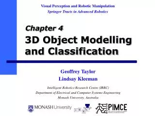
3D Object Modelling and Classification
Visual Perception and Robotic Manipulation Springer Tracts in Advanced Robotics. 3D Object Modelling and Classification. Chapter 4. Intelligent Robotics Research Centre (IRRC) Department of Electrical and Computer Systems Engineering Monash University, Australia. Geoffrey Taylor

3D Object Modelling and Classification
E N D
Presentation Transcript
Visual Perception and Robotic Manipulation Springer Tracts in Advanced Robotics 3D Object Modelling and Classification Chapter 4 Intelligent Robotics Research Centre (IRRC) Department of Electrical and Computer Systems Engineering Monash University, Australia Geoffrey Taylor Lindsay Kleeman
Contents • Introduction and motivation. • Split-and-merge segmentation algorithm • New method for surface type classification based on Gaussian image and convexity analysis • Fitting geometric primitives • Experimental results • Conclusions
Introduction • Motivation: enablea humanoid robotto perform ad hoctasks in a domesticor office environment. • Flexibility in anunknown environmentrequires data drivensegmentation to support object classification. Metalman: an upper-torso humanoid robot
Introduction • Object modelling in robotic applications: • CAD models (Kragić, 2001) • Generalized cylinders (Rao et al, 1989) • Non-parametric (Müller & Wörn, 2000) • Geometric primitives (Yang & Kak, 1986) • Many domestic objects can be adequately modelled with geometric primitives. • Colour/range data provided by robust stereoscopic light stripe scanner (Taylor et al, 2002).
Segmentation • Basic techniques: • Region Growing: iteratively grow seed segments. • Split-and-Merge: find region boundaries. • Clustering: transform and group points. • Region growing requires accurate range data for fitting primitives to small seed regions. • Split-and-Merge maintains large regions that can be robustly fitted to primitives.
Segmentation • Raw range/colour data from stereoscopic light stripe camera. • Calculate normal vector and surface type for each range element.
Segmentation • Remove rangediscontinuities and creases. • Fit primitives. • Compare best model to dominant surface type. • Split poorly modelled regions by surface type and fit primitives again.
Segmentation • Iteratively grow regions by adding unlabelled pixels that satisfy model. • Merge regions using iterative boundary cost minimization to compensate for over-segmentation.
Segmentation • Extract primitives and add texture using projected colour data. • Use models for object classification, tracking and task planning
Surface Type • Determine local shape of NxN element patch:
Classification methods • Conventional method: • Fit surface, calculate mean and Gaussian curvature • Classify based on curvature sign ( > 0, < 0, = 0) • Sensitive to noise (second-order derivatives required) • Arbitrary approximating function introduces bias. • Our novel method: • Based on convexity and principal curvatures. • Non-parametric (no approximating surface) • Robust to noise
Classification Number of non-zero principal curvatures Zero One Two Convexity convex concave neither
Surface representation Gaussian image Principal Curvatures • Determine number of principal curvatures from Gaussian image of surface patch.
Principal Curvatures • Spread of normal vectors in Gaussian image of patch indicates non-zero principal curvature. plane ridge/valley pit/peak/saddle
y amin min max x Principal Curvatures • Align central normal to z-axis. • Measure spread in direction using MMSE: • Optimize with respect to • Two solutions:(, e)max and (, e)min • Non-zero curvature whenemax > eth or emin > eth
n0 (n1 x n0) x d n1 n1 n0 n1 x n0 d d n1 x n0 (n1 x n0) x d Convexity Concave Convex
Convexity • For each element in patch, calculate: • Let S=Ncv/Ncc, ratio of convex to concave elements. • Global convexity given by dominant local property:
Surface Type Summary principal curvatures raw 3D scan surface type convexity
Fitting Primitives • Planes: • Principal component analysis • Spheres, cylinders, cones: • Minimize distance to fitted surface: • Levenberg-Marquardt numerical optimization. • Initial estimate of parameters required. • Choose model with minimum error, e < eth.
y a a min x Cylinder Estimation • Estimate cylinder axis from Gaussian image: Cylindrical region and axis Gaussian image and direction of minimum spread
Results • Box, ball and cup: Raw colour/range scan Discontinuities, surface type
Results • Box, ball and cup: Region growing, merging Extracted object models
Results • Bowl, funnel and goblet: Raw colour/range scan Discontinuities, surface type
Results • Bowl, funnel and goblet: Region growing, merging Extracted object models
Results • Comparison with curvature-based method: Non-parametric result Besl and Jain, 1988
Conclusions • Split-and-merge segmentation using surface type and geometric primitives is capable of modelling a variety of domestic objects using planes, spheres, cylinders and cones. • New surface type classifier based on principal curvatures and convexity provides greater robustness than curvature-based methods without additional computational cost.