Download
1 / 35
350 likes | 387 Views
This study focuses on the measurement of Electric Dipole Moment (EDM) using magnetic and electric fields in the KEK-RCNP experiment. It discusses the principle of the EDM measurement, systematic errors, field simulations, and experimental setups.

E N D
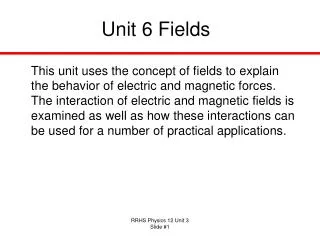
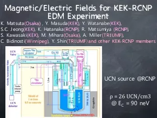
Magnetic/Electric Fields for KEK-RCNP EDM Experiment K. Matsuta(Osaka) , Y. Masuda(KEK), Y. Watanabe(KEK), S.C. Jeong(KEK), K. Hatanaka(RCNP), R. Matsumiya (RCNP), S. Kawasaki(KEK), M. Mihara(Osaka), A. Miller(TRIUMF), C. Bidinosti(Winnipeg), Y. Shin(TRIUMF)and other KEK-RCNP members UCN source @RCNP ρ = 26 UCN/cm3 @ EC = 90 neV
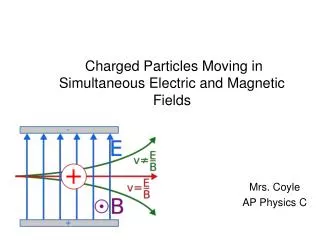
δdsta = h/{2PnEtc√N} nEDM Pncos(ω-ωo)tc RF frequency ω Principle of EDM measurement n spin s 1st RF pulse γH1t = π/2 ωo: 2μnHo ± 2dnE tc: precession time Ho 1 μT E 10 kV/cm (ω-ωo)tc UCN bottle E reversal for extraction of dn Pn : UCN polarization N : number of UCN
δdsta = h/{2PnEtc√N} nEDM Pncos(ω-ωo)tc RF frequency ω Principle of EDM measurement n spin s 1st RF pulse γH1t = π/2 ωo: 2μnHo ± 2dnE tc: precession time Ho 1 μT E 10 kV/cm (ω-ωo)tc UCN bottle E reversal for extraction of dn Pn : UCN polarization N : number of UCN
magnetic material Non-cylindrically symmetric field ∂B/∂z = 1 nT/m Magnetic shielding Systematic errors at ILL ×10-27 e.cm 1 Door cavity dipole -5.6 ±2.0 2 Other dipole fields 0.0 ±6.0 3 Quadrupole difference -1.3 ±2.0 4 v×E translational 0.0 ±0.03 5 v×E rotational 0.0 ±1.0 6 Second-order v×E 0.0 ±0.02 7 Hg light shift (geo phase) 3.5 ±0.8 8 Hg light shift (direct) 0.0 ±0.2 9 Uncompensated B drift 0.0 ±2.4 10 Hg atom EDM -0.4 ±0.3 11 Electric forces 0.0 ±0.4 12 Leakage currents 0.0 ±0.1 13 AC fields 0.0 ±0.01 Total -3.8 ±7.2 Sensitive magnetometer removes magnetized material. Spherical coil removes quadrupole component. reduced ∂B/∂z = 0.1 nT/m with small cell superparamagnetic material/ superconductor
Ramsey resonance for EDM Ramsey resonance UCN filling UCN detection 170 neV max VF + μH 210 neV ± 120 neV 90 neV 330 neV
Spherical coil π/2 RF coil Ramsey resonance with present UCN source EDM cell Door valve UCN valve Spin flipper Polarizer/analyzer Rotary valve UCN detector
π/2 RF coil EDM cell UCN storage timein the EDM Cell Silica + DLC coating τ = 119.5 ± 1.4 s Silica + CuBe Silica + CuBe Untreated Degreasing τ = 24.7 ± 0.9 s τ = 75.8 ± 2.3 s
tc= 100ms t t two coherent RF pulses Ramsey resonance 2009 π/2 π/2 Effect of Pncos(ω-ωo)tc visibility α = (Nmax – Nmin)/(Nmax + Nmin) = 0.9 -π (ω-ωo)tc = -5π π 5π -3π 3π -4π 4π 0 -2π 2π 200 mG
Ramsey resonance 2010 tc= 30 s t t two coherent RF pulses 1/30 Hz 30 s Ramsey fringe tc = 30 s , α= 0.33 H0 = 20 mG resonance freq.
Visibility as a function of tc 1/T2=(ω0 δB/B0)2 τ Where τ=λ/vucn S.Flipp et al. / NIM A 598 (2009) 571 T2 〜 50 s
δBz=4nT δBz/B0 〜 0.2% dBz/dz =25 [nT/m] EDM cell Bz field distribution ω0(δB/B0) =2π (60Hz)×(0.2%) = 0.75 1/s τ = λ/vucn= (4V/S)/ vucn= 0.04 sec Consistent with The experimental T2 1/T2=(ω0 δB/B0)2 τ = 1/44 1/s
Trim coil adjusted
Z Y Observation 3D field simulation(OPERA-3d) X Geomagnetic field Simulation
消磁回路図 6回巻き 1回巻き 100Ω 1μF 0.1Ω 消磁のヒステリシスループの軌跡 H(A/m) B(T)
Z X 磁気シールドの下の穴の部分に煙突があるとき、ないときの比較 Geomagnetic field Only holes Z 80 60 40 X 20 0 Z(cm) Z(cm) -20 -40 -60 Chimney -80
Multi-layer suppression Field simulation(OPERA-3d) Z Y X Geomagnetic field
Z 2D Magnetic field distribution for 2msize model Y 1nT Compensationコイル X
Z=0 Y=0 2m size coil 1nT 4m size coil
Z Y 1/5 scale model of Compensation coil X 3axes – flux gate sensor
Experimental setup for EDMat New UCN source Increase UCN transport efficiency 25
Our data 105 Extrapolation ? 10kV/cm Phys. Lett. A 376 (2012) 1347 IEEE TRANSACTIONSON POWER APPARATUS AND SYSTEMS, VOL. PAS-88, 1969
Silica HV Cell Electric field simulation for HV cell strong field have to avoid discharge homogeneity ~ 10-2 should be homogeneous to avoid vxE effect for rotational flow
E v EDM Cell Er vxEr 1 Er df = μ V c2 E Er x x (Degree of rotational flow) = (6 x 10-22 ecm) E
Summary Present dB/dz 〜 25 nT/m or δBz = 4nT tc = 30 s Ramsey ts = 120 s T1 〜 1000 s T2 =50 s B field Improvement 4 layer shield Demagnetization Compensation coil 1 nT/m 0.1nT/m With Fluxgate and K magnetometer Structure Designing for small leakage and good homogeneity And good breakdown character with Xe gas E filed 2013 Test of the New UCN source 2013〜2014 High voltage application test EDM SC polarizer Xe co-magnetometer 2015? TRIUMF