Download
1 / 7
70 likes | 83 Views
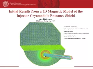
This document presents the initial results and findings from a 3D magnetic model of the injector cryomodule entrance shield. The study includes comparisons with CAD and OPERA models, as well as analysis of field components and electron tracking. The document concludes with preliminary conclusions and an invitation for further development.

E N D
Initial Results from a 3D Magnetic Model of theInjector Cryomodule Entrance ShieldJim CrittendenERL General Meeting, 2 April 2009 Post-meeting annotations: 1) Wrong sign in two coils resulted in zero net kick in each plane 2) Bug found: current densities were 200 A/cm^2 instead of 110 A/cm^2 3) Note that mu metal thickness is 50 mils
CAD and OPERA Model Comparison CAD pictures from Eric Chojnacki 2 April 2009 ERL General / J.A.Crittenden
B-H Curve for AD-MU 80 Information and reasoning by Eric Chojnacki. “Magnetic Shielding in a Cryogenic Environment” by Arentz, Johnson and Dant 300 K 77 K 2 April 2009 ERL General / J.A.Crittenden
Field Components on Beam Axis Horizontal Component 0 < BX < 0.011 Gauss Integral: -0.08 Gauss-cm (Calculation accuracy) 100 Amps in both horizontal and vertical corrector coils. Shield at Z = 0 cm -25 < Z < 25 cm Vertical Component -0.02 < BY < 0.2 Gauss Integral: -2.7 Gauss-cm (Contribution by shield) Longitudinal Component -7 < BZ < 11 Gauss Integral: 2.7 Gauss-cm (Contribution by coil) 2 April 2009 ERL General / J.A.Crittenden
Systematic Check with Mu Metal Turned Off Horizontal Component BX < 10-15 Gauss (Calculation accuracy) 100 Amps in both horizontal and vertical corrector coils. Shield at Z = 0 cm -25 < Z < 25 cm Vertical Component BY < 10-15 Gauss (Calculation accuracy) Longitudinal Component -8 < BZ < 8 Gauss (Contribution by coil) 2 April 2009 ERL General / J.A.Crittenden
Electron Tracking 250 keV electrons 11 x 11 entrance grid over 2 x 2 cm tracked for 75 cm 2 April 2009 ERL General / J.A.Crittenden
Preliminary Conclusions • The shape of the shield does not introduce as much distortion in the electron trajectories as observed • The 3D model is available for further development • All suggestions welcome ERL@CESR/ J.A.Crittenden 2 April 2009