Download
1 / 73
730 likes | 743 Views
Explore the OSI model, LAN devices, IP addressing, and more in this comprehensive review. Understand the importance of layered models, network protocols, and communication processes. Dive into the fundamentals of networking technologies and protocols.

E N D
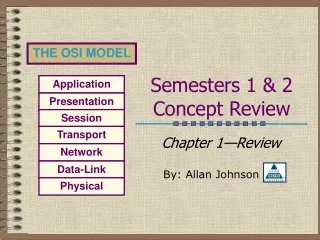
Semesters 1 & 2Concept Review Chapter 1—Review By: Allan Johnson
Table of Contents • Review the OSI Model • LAN Devices & Technologies • IP Addressing • CIDR Notation • Routing • Transport Layer Go There! Go There! Go There! Go There! Go There! Go There!
Protocol de retea - definitie • un protocol defineşte formatul şi ordinea mesajelor schimbate între două sau mai multe entităţi ce comunică între ele, precum şi acţiunile ce sunt întreprinse odată cu transmiterea sau recepţia unui mesaj sau a unui alt eveniment.
Review The Model Open Systems Interconnected Reference Model Table of Contents
Why A Layered Model? • Reduces complexity • Standardizes interfaces • Facilitates modular engineering • Ensures interoperable technology • Accelerates evolution • Simplifies teaching & learning Application Presentation Session Transport Network Data-Link Physical
Application Layer • Provides network services (processes) to applications. • For example, a computer on a LAN can save files to a server using a network redirector supplied by NOSs like Novell. • Network redirectors allow applications like Word and Excel to “see” the network. Application Presentation Session Transport Network Data-Link Physical
Presentation Layer • Provides data representation and code formatting. • Code formatting includes compression and encryption • Basically, the presentation layer is responsible for representing data so that the source and destination can communicate at the application layer. Application Presentation Session Transport Network Data-Link Physical
Session Layer • Provides inter-host communication by establishing, maintaining, and terminating sessions. • Session uses dialog control and dialog separation to manage the session • Some Session protocols: • NFS (Network File System) • SQL (Structured Query Language) • RCP (Remote Call Procedure) • ASP (AppleTalk Session Protocol) • SCP (Session Control Protocol) • X-window Application Presentation Session Transport Network Data-Link Physical
Transport Layer • Provides reliability, flow control, and error correction through the use of TCP. • TCP segments the data, adding a header with control information for sequencing and acknowledging packets received. • The segment header also includes source and destination ports for upper-layer applications • TCP is connection-oriented and uses windowing. • UDP is connectionless. UDP does not acknowledge the receipt of packets. Application Presentation Session Transport Network Data-Link Physical
Network Layer • Responsible for logically addressing the packet and path determination. • Addressing is done through routed protocols such as IP, IPX, AppleTalk, and DECnet. • Path Selection is done by using routing protocols such as RIP, IGRP, EIGRP, OSPF, and BGP. • Routers operate at the Network Layer Application Presentation Session Transport Network Data-Link Physical
Data-Link Layer • Provides access to the media • Handles error notification, network topology issues, and physically addressing the frame. • Media Access Control through either... • Deterministic—token passing • Non-deterministic—broadcast topology (collision domains) • Important concept: CSMA/CD Application Presentation Session Transport Network Data-Link Physical
Physical Layer • Provides electrical, mechanical, procedural and functional means for activating and maintaining links between systems. • Includes the medium through which bits flow. Media can be... • CAT 5 cable • Coaxial cable • Fiber Optics cable • The atmosphere Application Presentation Session Transport Network Data-Link Physical
Application Application Data Presentation Presentation Data Session Session Data Segments Transport Transport Packets Network Network Data-Link Data-Link Frames Physical Physical Bits Peer-to-Peer Communications • Peers communicate using the PDU of their layer. For example, the network layers of the source and destination are peers and use packets to communicate with each other.
Encapsulation Example • You type an email message. SMTP takes the data and passes it to the Presentation Layer. • Presentation codes the data as ASCII. • Session establishes a connection with the destination for the purpose of transporting the data. Application Presentation Session Transport Network Data-Link Physical
Encapsulation Example • Transport segments the data using TCP and hands it to the Network Layer for addressing • Network addresses the packet using IP. • Data-Link then encaps. the packet in a frame and addresses it for local delivery (MACs) • The Physical layer sends the bits down the wire. Application Presentation Session Transport Network Data-Link Physical
LAN Devices & Technologies The Data-Link & Physical Layers Data-Link Physical Table of Contents
Devices • What does it do? • Connects LAN segments; • Filters traffic based on MAC addresses; and • Separates collision domains based upon MAC addresses. What layer device?
Devices • What does it do? • Since it is a multi-port bridge, it can also • Connect LAN segments; • Filter traffic based on MAC addresses; and • Separate collision domains • However, switches also offer full-duplex, dedicated bandwidth to segments or desktops. What layer device?
Devices • What does it do? • Concentrates LAN connections from multiple devices into one location • Repeats the signal (a hub is a multi-port repeater) What layer device?
Devices • What does it do? • Interconnects networks and provides broadcast control • Determines the path using a routing protocol or static route • Re-encapsulates the packet in the appropriate frame format and switches it out the interface • Uses logical addressing (i.e. IP addresses) to determine the path What layer device?
LAN Technologies Three Most Common Used Today in Networking
Ethernet/802.3 • Cable Specifications: • 10Base2 • Called Thinnet; uses coax • Max. distance = 185 meters (almost 200) • 10Base5 • Called Thicknet; uses coax • Max. distance = 500 meters • 10BaseT • Uses Twisted-pair • Max. distance = 100 meters • 10 means 10 Mbps
Ethernet/802.3 • Ethernet is broadcast topology. • What does that mean? • Every devices on the Ethernet segment sees every frame. • Frames are addressed with source and destination ______ addresses. • When a source does not know the destination or wants to communicate with every device, it encapsulates the frame with a broadcast MAC address: FFFF.FFFF.FFFF • What is the main network traffic problem caused by Ethernet broadcast topologies?
Ethernet/802.3 • Ethernet topologies are also shared media. • That means media access is controlled on a “first come, first serve” basis. • This results in collisions between the data of two simultaneously transmitting devices. • Collisions are resolved using what method?
Ethernet/802.3 • CSMA/CD (Carrier Sense Multiple Access with Collision Detection) • Describe how CSMA/CD works: • A node needing to transmit listens for activity on the media. If there is none, it transmits. • The node continues to listen. A collision is detected by a spike in voltage (a bit can only be a 0 or a 1--it cannot be a 2) • The node generates a jam signal to tell all devices to stop transmitting for a random amount of time (back-off algorithm). • When media is clear of any transmissions, the node can attempt to retransmit.
Address Resolution Protocol • In broadcast topologies, we need a way to resolve unknown destination MAC addresses. • ARP is protocol where the sending device sends out a broadcast ARP request which says, “What’s you MAC address?” • If the destination exists on the same LAN segment as the source, then the destination replies with its MAC address. • However, if the destination and source are separated by a router, the router will not forward the broadcast (an important function of routers). Instead the router replies with its own MAC address.
IP Addressing Subnetting Review Network Table of Contents
Logical Addressing • At the network layer, we use logical, hierarchical addressing. • With Internet Protocol (IP), this address is a 32-bit addressing scheme divided into four octets. • Do you remember the classes 1st octet’s value? • Class A: 1 - 126 • Class B: 128 - 191 • Class C: 192 - 223 • Class D: 224 - 239 (multicasting) • Class E: 240 - 255 (experimental)
N N N H N N H H N H H H Network vs. Host Class A: 27 = 126 networks; 224 > 16 million hosts Class B : 214 = 16,384 networks; 216 > 65,534 hosts Class C : 221 > 2 million networks; 28 = 254 hosts
Why Subnet? • Remember: we are usually dealing with a broadcast topology. • Can you imagine what the network traffic overhead would be like on a network with 254 hosts trying to discover each others MAC addresses? • Subnetting allows us to segment LANs into logical broadcast domains called subnets, thereby improving network performance.
Four Subnetting Steps • To correctly subnet a given network address into subnet addresses, ask yourself the following questions: • How many bits do I need to borrow? • What’s the subnet mask? • What’s the “magic number” or multiplier? • What are the first three subnetwork addresses? • Let’s look at each of these questions in detail
1. How many bits to borrow? • First, you need to know how many bits you have to work with. • Second, you must know either how many subnets you need or how many hosts per subnet you need. • Finally, you need to figure out the number of bits to borrow.
1. How many bits to borrow? • How many bits do I have to work with? • Depends on the class of your network address. • Class C: 8 host bits • Class B: 16 host bits • Class A: 24 host bits • Remember: you must borrow at least 2 bits for subnets and leave at least 2 bits for host addresses. • 2 bits borrowed allows 22- 2 = 2 subnets
1. How many bits to borrow? • How many subnets or hosts do I need? • A simple formula: • Total Bits = Bits Borrowed + Bits Left • TB = BB + BL • I need x subnets: • I need x hosts: • Remember: we need to subtract two to provide for the subnetwork and broadcast addresses.
1. How many bits to borrow? • Class C Example: 210.93.45.0 • Design goals specify at least 5 subnets so how many bits do we borrow? • How many bits in the host portion do we have to work with (TB)? • What’s the BB in our TB = BB + BL formula? (8 = BB + BL) • 2 to the what power will give us at least 5 subnets? 23 - 2 = 6 subnets
1. How many bits to borrow? • How many bits are left for hosts? TB = BB + BL 8 = 3 + BL BL = 5 • So how many hosts can we assign to each subnet? 25 - 2 = 30 hosts
1. How many bits to borrow? • Class B Example: 185.75.0.0 • Design goals specify no more than 126 hosts per subnet, so how many bits do we need to leave (BL)? • How many bits in the host portion do we have to work with (TB)? • What’s the BL in our TB = BB + BL formula? (16 = BB + BL) • 2 to the what power will insure no more than 126 hosts per subnet and give us the most subnets? 27 - 2 = 126 hosts
1. How many bits to borrow? • How many bits are left for subnets? TB = BB + BL 16 = BB + 7 BL = 9 • So how many subnets can we have? 29 - 2 = 510 subnets
1 1 1 128 64 32 16 8 4 2 1 2. What’s the subnet mask? • We determine the subnet mask by adding up the decimal value of the bits we borrowed. • In the previous Class C example, we borrowed 3 bits. Below is the host octet showing the bits we borrowed and their decimal values. We add up the decimal value of these bits and get 224. That’s the last non-zero octet of our subnet mask. So our subnet mask is 255.255.255.224
3. What’s the “magic number?” • To find the “magic number” or the multiplier we will use to determine the subnetwork addresses, we subtract the last non-zero octet from 256. • In our Class C example, our subnet mask was 255.255.255.224. 224 is our last non-zero octet. • Our magic number is 256 - 224 = 32
Last Non-Zero Octet • Memorize this table. You should be able to: • Quickly calculate the last non-zero octet when given the number of bits borrowed. • Determine the number of bits borrowed given the last non-zero octet. • Determine the amount of bits left over for hosts and the number of host addresses available.
4. What are the subnets? • We now take our “magic number” and use it as a multiplier. • Our Class C address was 210.93.45.0. • We borrowed bits in the fourth octet, so that’s where our multiplier occurs • 1st subnet: 210.93.45.32 • 2nd subnet: 210.93.45.64 • 3rd subnet: 210.93.45.96 • We keep adding 32 in the fourth octet to get all six available subnet addresses.
Host & Broadcast Addresses • Now you can see why we subtract 2 when determining the number of host address. • Let’s look at our 1st subnet: 210.93.45.32 • What is the total range of addresses up to our next subnet, 210.93.45.64? • 210.93.45.32 to 210.93.45.63 or 32 addresses • .32 cannot be assigned to a host. Why? • .63 cannot be assigned to a host. Why? • So our host addresses are .33 - .62 or 30 host addresses--just like we figured out earlier.
CIDR Notation A Different Way to Represent a Subnet Mask Network Table of Contents
CIDR Notation • Classless Interdomain Routing is a method of representing an IP address and its subnet mask with a prefix. • For example: 192.168.50.0/27 • What do you think the 27 tells you? • 27 is the number of 1 bits in the subnet mask. Therefore, 255.255.255.224 • Also, you know 192 is a Class C, so we borrowed 3 bits!! • Finally, you know the magic number is 256 - 224 = 32, so the first useable subnet address is 197.168.50.32!! • Let’s see the power of CIDR notation.
202.151.37.0/26 • Subnet mask? • 255.255.255.192 • Bits borrowed? • Class C so 2 bits borrowed • Magic Number? • 256 - 192 = 64 • First useable subnet address? • 202.151.37.64 • Third useable subnet address? • 64 + 64 + 64 = 192, so 202.151.37.192