Download
1 / 29
310 likes | 560 Views
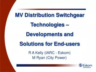
MV Distribution Switchgear Technologies – Developments and Solutions for End-users. R A Kelly (IARC - Eskom) M Ryan (City Power). Synopsis. Alternative solutions to oil-filled switchgear used in MV distribution Eskom et al experience & rationale

E N D
MV Distribution Switchgear Technologies – Developments and Solutions for End-users R A Kelly (IARC - Eskom) M Ryan (City Power)
Synopsis • Alternative solutions to oil-filled switchgear used in MV distribution • Eskom et al experience & rationale • safety, environmental and economic considerations • Focus on secondary distribution switchgear – i.e. RMUs • Management of existing oil-filled switchgear
Introduction • MV oil-filled switchgear widespread in EDI • Generally reliable! • Switchgear installed < 1970 – reached end of its design life and may be unsafe • unmainted switchgear • over-stressed • DMO • modifications • inadequately trained operators • Failures can be castastrophic
Introduction • “In general, oil-filled switchgear has a proven record of reliability and performance. Failures are rare but, where they occur, the results may be catastrophic. Tanks may rupture, resulting in the ejection of burning oil and gas clouds, causing death or serious injury to persons and major damage to plant and buildings in the vicinity of the failed equipment. Accident experience has shown that failure usually occurs at, or shortly after, operation of the equipment. Thus, the way switchgear is operated, its condition and the circumstances existing in the system at the time of operation, to a large extent, determines whether the equipment will safely perform its duty.” • Clause 5, HSE 483/27 – Oil-filled electrical distribution and other switchgear’
Introduction • Responsibility of users • OHS Act No. 85 of 1993 • Acceptably safe environment • Reasonable measures to mitigate against possible dangers • Developments in switchgear technologies have presented users with a compelling argument for the use of lower cost, safer and more reliable equipment • Insulating/interrupting medium of gas / vacuum • ‘sealed for life’
History of MV S/G in SA EDI • For many years – primary insulation/interrupting medium was oil • Historically - interval and event-based maintenance schedule • Alarming trend – inadequately maintained • Maintenance simply not being scheduled • pressure on maintenance budgets • increasingly difficult to schedule onerous outages required for maintenance • ‘Run-to-failure’ philosophy
History of MV S/G in SA EDI • Why maintain? • moving parts, aging oil • most OF S/G ‘free-breathing’ • ‘uncontrolled’ environment • switchgear vs other oil filled equipment • The result? • Gradual deterioration in the insulating and interrupting properties of oil • Increased probability of mechanism failure • Increased risk and number of failures with associated injuries / fatalities
History of MV S/G in SA EDI • Failures due to use of sub-standard oil-type MV HRC fuses used in RMUs • Serious risk associated with inferior quality, non type tested fuses which entered the SA market • unable to interrupt rated current (failed at <25% rated current) • inadequate oil-tight seals
History of MV S/G in SA EDI • Other insulating mediums: • ‘insulation-enclosed’ epoxy resin switchgear • inadequate maintenance & training • adverse environmental conditions • Air-filled enclosures • metal-clad switchgear, cable terminations • not exempt from poor track record (*3.2) • requires correct application of NRS 012 • 4 types of terminations & live conductors in air, creepage distances (OD & ID) • creepage still required indoors!
Alternative solutions • Key issue: improved safety • internal arc rating (IAC) • What is IAC switchgear? • ensures the safe venting of gases away from operator and/or public • IAC only possible with ‘dry-arcs’ • can be simulated in laboratory • Simply not possible or practical for oil-filled switchgear - uncontrollable • At best OF S/G having air-filled internal arc tested cable boxes may be available
Alternative solutions • Arc energy = f (voltage, S/C current, time) • Energy absorbed by person = f (arc energy, distance, PPE)
Alternative solutions • Inadequate pressure release mechanisms
Alternative solutions • SF6 gas-insulated switchgear • preferred gas for filling enclosures • superior insulation and arc extinction properties • odourless, non-toxic, chemically inert, non-flammable • classified as a greenhouse gas • management and handling • under positive pressure • <1% leakage – >30 years service • toxic products – decomposition due to arcing • not considered a problem – ‘sealed for life’
Safety Considerations • Safety: • achieved by reducing risk to a tolerable level • risk = comb. (probability, severity) of a harm • Tolerable risk: • search for optimal balance between ‘absolute safety’, demands to be met by product and factors such as benefit to user, suitability for purpose and cost • Need to continually review ‘tolerable level of risk’ – when developments in technology and knowledge can lead to economically feasible improvements
Risk Reduction • OHS Act has a general duty clause – reasonable precautions • PPE – last line of defense! • No local electrical safety regulations relating to internal arc • NFPA 70E • establish boundaries (LRPF) • hazard awareness • appropriate PPE • Arc flash analysis
Risk Reduction • IEC IAC provides a tested level of protection • under normal operating conditions • not under maintenance conditions • not concerned with service continuity • ‘Supplementary’ measures • arc detection, CLDs, arc suppressors, pressure relief devices, remote control, motorised racking devices, transfer of withdrawable parts with front doors closed • requires a co-ordinated approach
Risk Reduction • Existing switchgear where elevated risk still exist: • May have to implement restrictive operating procedures • QoS and COUE vs • cost of implementing oil-filled switchgear management programmes to mitigate against potential dangers of older oil-filled switchgear • both are costly
Specifications for new S/G • 1998 – internal arc testing of primary S/G • 2002 – specification of IAC secondary switchgear (RMUs) • Operator and public safety under the spotlight • recent catastrophic failures of S/G • elevating arc flash safety to new levels • Involved in development and re testing of all MV S/G using SANS/IEC 62271-200 and SANS/IEC 61330 • IAC philosophy revisted
Specifications for new S/G • Primary switchgear: • AR-BFL (SANS 62271-200) • 25kA 0,2 s (12kV & 24kV) • arc detection system • venting upwards, room dimensions, pressure relief • Secondary switchgear: • AF-BFLR (SANS 61330) • 20kA 0,5 s (12kV) 16kA 0,5 s (24kV) • venting upwards – 2m duct
Economic Considerations • Any sound engineering solution • total cost of ownership • ‘life-cycle costing’ • Initial capital cost (cost of acquisition) • Future upgrade/replacement costs • Cost of technical losses • Cost of unserved energy • Maintenance costs (normally periodic) • Dismantling / residual costs • Liability costs • Operating costs
Economic Considerations • Cost of unserved energy
Economic Considerations • Eskom LCC comparison in 2002, 2004 between • oil-filled S/G requiring routine maintenance every 3 years (min) • SF6 gas-insulated S/G – ‘maintenance free’ (not requiring a prolonged outage) • Alternatives analysed for acquisition, use and disposal phases
Life-Cycle Costs (Rands) Economic Considerations 140,000.00 120,000.00 Others Unserved Energy Maintenance 100,000.00 Acquisition 80,000.00 60,000.00 40,000.00 20,000.00 0.00 OIL RMU SF6 RMU
Economic Considerations • Key differences: • purchase price (cost of acquisition) • ‘maintenance free’ SF6 equipment • SF6 enclosure – ‘non accessible’ • every 12 years, 4 hours • visual inspections, operating mechanism maintenance, cleaning • Other factors: • transport, storage, replenishment of oil • commissioning costs for oil-filled S/G • risk of contamination
Management of oil-filled S/G • Recommendations based on HSE 483/27 (Oil-filled electrical distribution and other S/G) • Identification & classification of all S/G • Inventory • equipment information • fault levels, modifications, DMO • Over-stressed, DMO, un-maintained switchgear • live operation & access restricted • if possible, reduce fault levels • prioritise replacement
Management of oil-filled S/G • other switchgear • proper maintenance • oil-level indicators / checks for oil-leaks • Maintenance • Phased replacement program • HRC fuses: • installation, replacement (SANS/IEC 62271-105) • quality (SANS/IEC 60282) • if necessary, prevent live operation
Conclusions • Ever increasing focus on human safety, service delivery and cost reduction! • Eskom and other major utilities have responded to the changing risk profile in the light of developments in both technology and knowledge • Sought solutions offering not only a reduction in risk but also: • reduced total cost of ownership • Air and/or gas-insulated S/G utilising vacuum and/or SF6 interrupting technologies provide users with equipment that meets required specifications and performance levels