Download
1 / 56
600 likes | 904 Views
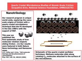
Micro-Electro-Mechanical Systems: These Squeaky Wheels will get no Grease. Jacqueline Krim, Department of Physics. Nanotribology Lab. NC State. Iron on copper Temp. = 4 K. M.F. Crommie, C.P. Lutz, D.M. Eigler, E.J. Heller., Surf. Rev. and Lett. 2 (1) , 127-137 (1995).

E N D
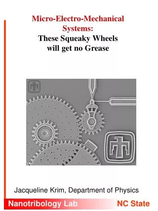
Micro-Electro-Mechanical Systems: These Squeaky Wheels will get no Grease Jacqueline Krim, Department of Physics Nanotribology Lab NC State
Iron on copper Temp. = 4 K M.F. Crommie, C.P. Lutz, D.M. Eigler, E.J. Heller.,Surf. Rev. and Lett. 2(1), 127-137 (1995) R. Overney and E. Meyer, MRS Bulletin, May 1993, p. 26. U. Kunze and B. Klehn, Adv. Mat.11, 1473 (1999) Flourocarbon / Hydrocarbon mixtures. 70 nm line widths Polymer mask over SiO2 film on Si, etched in HF. 50 nm line widths
Atomic Scale Engines: Cars and Wheels M. Porto et al., PRL 84, 1608 (2000)
Every week Apply a few drops of engine oil to the spark and throttle cross-shaft brackets Apply sufficient amounts of engine oil to all brake clevised, oiler, and cross-shaft brackets, at least 12 locations Force a “grease gun full”(half cup) of grease into the universal joint Pack the ball joints of the steering mechanism with grease more….. Every Day Check Oil in Engine, oil lubricated clutch, tranmission, and differential gear housing Turn grease cup caps on the 8 spring bolts, one turn Apply a few drops of engine oil to the tie rod clevises Turn the grease cup on the fan support …….more 1916 Maxwell Owner’s Manual
2000 miles Drain rear axle, flush with kerosene and refill. Drain crank case, flush with kerosene, and refill (several quarts) Jack up car by the frame, pry spring leaves apart, and insert graphite grease between the leaves. Monthly Force a “grease gun full” of grease into the engine timing gear. Force a “grease gun full” of grease into the steering gear case. Apply a few drops of 3-in-1 oil to the magneto bearing. Turn the grease cup on the generator drive shaft, one turn. Turn the grease cup on the drive shaft bearing, one turn. ……more 1916 Maxwell Owner’s Manual
Regularly Check engine valve action Inspect ignition wiring. Check battery fluid level and color. Inspect cooling system for leaks. Check fan belt tension. Inspect steering parts. Tighten body and fender bolts. Check effectiveness of brakes. more….. Biweekly Check engine compression. Listen for crankshaft bearing noises. Clean and regap spark plugs. Adjust carburetor mixture. Clean gasoline strainer. Drain water from carburetor bowl . Inspect springs. More…. 1916 Maxwell Owner’s Manual
MicroElectro Mechanical Systems An emerging cutting-edge technology which relies on microfabrication of small scale IC compatible mechanical components Advantages: Mass-fabrication, low-cost and IC integration Application : Whole new line of applications, limited only by imagination • MEMS Microsurgery devices • Miniature valves, pumps • MEMS accelerometer used in Airbags
MEMS Application Photo Courtesy M. Adrian Michalicek, University of Colorado at Boulder
MEMS Tribology Issues Surface effects that dominate bulk effectsHigh temperature processing conditionsLubricant deliveryLubricant replenishment Tribological issues related: • Stiction (Release and/or In-use) • Friction and wear Stiction: Unintentional adhesion of microstructure surfaces where the restoring forces are unable to overcome interfacial forces
Release related stiction Adhesion of micromachined structures to the underlying substrate after the final sacrificial layer etch • Caused mainly by liquid capillary forces Photo Courtesy University of California at Berkley
Approaches to solving release related stiction • Self-assembled monolayer (SAMs) OTS, FDTS, DDMS - Capillary pull can be made into a push if the contact angle is made larger than 90 ° - Due to hydrophobicity of these coatings, capillary forces responsible for release-related stiction are eliminated Photo Courtesy University of California at Berkley
Alternate release methods • Supercritical carbon dioxide drying of Microstructures - Avoidance of liquid-vapor interfaces through supercritical fluid - Allows samples to be dried without any surface tension, thus reducing the likelihood of stiction • Freeze sublimation drying
In-use stiction and/or Friction Permanent adhesion through acceleration or electrostatic forces and/or adhesive forces between surfaces causing permanent device failure • developing stiction reducing chemical additives for final rinse stages • development of vapor-phase lubricants for use in extreme MEMS operating environments • A knowledge of nanotribology is required, as contact areas may include only tens of atoms! Approaches towards solving Stiction/Friction
Nanotribology and the Atomic-Scale Origins of Friction: What Once Was Old Is New Again. v m Ff mg FN Ff = FN Amontons, 1699 v m F F = ma Newton, 1686 Nanotribology Lab NC State
v m Ff mg FN Classical Laws of Friction: 1) Ff = FN 2) independent of apparent contact area 3) independent of sliding speed depends on whether object is at rest or moving - “static friction” vs. “kinetic friction”. 1, 2 Guillaume Amontons, 1699 3 Charles-Augustin de Coulomb, 1785 s k Meanwhile, for solid-liquid interfaces, “viscous friction” applies, where,
Leonardo da Vinci Codex Atlanticus Codex Arundel ca. 1500 k = 0.25 Charles-Augustin de Coulomb Théorie des Machines Simple 1785
QCM: unconfined geometry, “viscous friction”, no static friction • SFA: Confined “planar” geometry, higher friction levels, “barrier to induce motion” always observed • LFM: Confined “point” geometry, highest friction levels, static friction always observed. J. Krim, Scientific American, Oct. 1996.
SFA Measurement S.E. Campbell, G. Luengo, V.I. Srdanov, F. Wudl, and J.N. Israelachvili, Nature, 382, 520-522 (1996). Compared toluene on mica to C60/toluene solution on mica. Found that C60 formed 1-2 monolayers on the mica--and these adsorbed layers “possess unusually high fluidity and are easily disrupted.” Found that the viscous response of the fluid near the mica surface was completely different for the C60/toluene solution as compared to the toluene alone. The C60 toluene solution exhibited full-slip boundary conditions. Does this imply it will be a good additive to lubricants? Toluene alone C60/Toluene Solution
AFM Measurements Scan speed: 500 nm/sec with silicon nitride cantilever 10% C60/Toluene solution
AFM Measurements 50 angstroms 60 angstroms mica under toluene, force error image mica under toluene, lateral force image mica under ~20% C60/toluene solution, force error image
C60 Rotation 109 Hz For Ag(111), the C60 molecules in the second layer rotate at frequencies matching that of bulk C60. E.I. Altman and R.J. Colton, Surface Science 295 (1993) 13-33 Ag(111) < 1 Hz For Ag(111), the C60 molecules in the first monolayer do rotate, but slowly. E.I. Altman and R.J. Colton, Surface Science 295 (1993) 13-33 Ag(111) 0 Hz When C60 molecules form a monolayer on Cu(111), the molecules lock in to a specific direction on the terraces and the free rotation is suppressed. T. Sakurai et al, Applied Surface Science 87/88 (1995) 405-413. Cu(111) Ag(111) Control
AFM Results The films were evaporated in UHV conditions onto freshly cleaved mica surfaces. They were then transferred to a liquid cell and completely submerged in methanol for the AFM measurements. The measurements were acquired under methanol in order to avoid capillary effects.
Single crystal quartz Metal film electrode Quartz Crystal Microbalance
A. B. Figure 8
Measuring friction with a quartz crystal microbalance (QCM) • Thin crystal disk oscillates in a shear mode • Adsorbed material lowers the resonant frequency • If the shear stress is below about 103 N/m2, it will “slip” enough to be detected by the QCM: • The slip time is deduced from Q and f: (Krim and Widom, PRB, v. 38, n.17, 1988)
QCM Results Toluene on C60/Ag Toluene on Ag
QCM Results Toluene on Ag Toluene on Ag/C60 Here, we find that C60 is sticky, while toluene is slippery.
“Existing molecular scale test methods do not duplicate the operating P-V space of micromachines” -- M.T. Dugger, Sandia Labs Proceedings of NIST Nanotribology Workshop Gaithersburg, MD March 13-15, 2000 They also do not duplicate the operating P-V space of macroscopic machines…. 1000 atomistic simulation 800 AFM/IFM 600 microengine speed record Pressure, MPa 400 micromachines 200 SFA 0 0 50 100 150 200 250 800 1000 Velocity, mm/s STM-QCM P = 0 - 1000 GPa V = 100 - 3000 mm/s Contact radius = 10 nm - 1 m
Alternate approaches are required to study MEMS lubricants. “Existing molecular scale test methods do not duplicate the operating P-V space of micromachines” -- M.T. Dugger, Sandia Labs Proceedings of NIST Nanotribology Workshop Gaithersburg, MD March 13-15, 2000 1000 atomistic simulation 800 AFM/IFM 600 microengine speed record Pressure, MPa 400 micromachines 200 SFA 0 0 50 100 150 200 250 800 1000 Velocity, mm/s STM-QCM P = 0 - 1000 GPa V = 100 - 3000 mm/s Contact radius = 10 nm - 1 m
Surface micromachined device to investigate friction & wear Photo Courtesy University of California at Berkley
Comb-drive Photo courtesy Sandia National Laboratories
Why vapor-phase lubricants? • semiconductor-like fabrication of MEMS devices • small size • monolithic nature of micromachines Difficulties in lubricating MEMS devices because of Vapor phase may ultimately prove to be an effective and perhaps exclusive means to deliver and/or replenish lubricants
Current focus on: • Development of realistic laboratory test set-ups which are both well controlled and relevant to operating machinery • Understanding the chemical and tribochemical reaction which occur in sliding contact • Characterization of the microstructural and mechanical properties of the micromachined contact region
Scanning Tunneling Microscope Quartz Crystal Microbalance STM-QCM metal tip film metal electrodes quartz disk
stationary vibrating 500 × 500 nm2 STM tip Tunneling current Metal electrode Quartz
Desirable Properties of a MEMS lubricant • Low friction • Low wear • Effective as very thin film • Uniform adhesion to substrate • Durable and Replenishable • Specificity • Usable in extreme environments (temperature, pressure) TCP is known to exhibit many of these properties in macroscopic tests. (downside: possible corrosion) QUESTION: Does it exhibit these same favorable properties in nanometer-scale tests using STM-QCM? TCP in purified form P O C H
Experimental System TCP vapor P O C TCP film H Metal substrate 3D-TRICRESYL PHOSPHATE (TCP) Quartz Crystal Microbalance (QCM) Atomic-scale studies of an anti-wear additive proven effective in extreme environments of high temperature and pressure.
O C P H TRICRESYL PHOSPHATE (TCP)/Fe M. Abdelmaksoud, J. Bender and J. Krim, Trib. Lett. submitted
O C P H TCP slip times are comparable to those of physisorbed monolayers!
TCP at high temperature: Polymeric material Formation observed in combination with oxygen gas uptake, but only for iron substrates. How does this film respond to tribological contact?
STM-QCM of 10 Å TBPP film Room Temperature QCM OFF QCM ON 200 × 200 nm2 Liquid TBPP cannot diffuse back into the rubbed region faster than the QCM vibrational speed. Therefore, an image can be obtained when the QCM is vibrating.
STM-QCM of 10 Å TBPP film After Heating 40 × 40 nm2 F = + 0.6 Hz After annealing, the polymeric surface is more conducting , and ‘nonrigid’.