L CM Introduction
170 likes | 189 Views
Learn about the construction and technology behind Liquid Crystal Displays (LCDs), including different modes and viewing angles. Discover the differences between TN and STN LCDs and how to drive and backlight an LCD. Explore the various types of LCD modules and applications.

L CM Introduction
E N D
Presentation Transcript
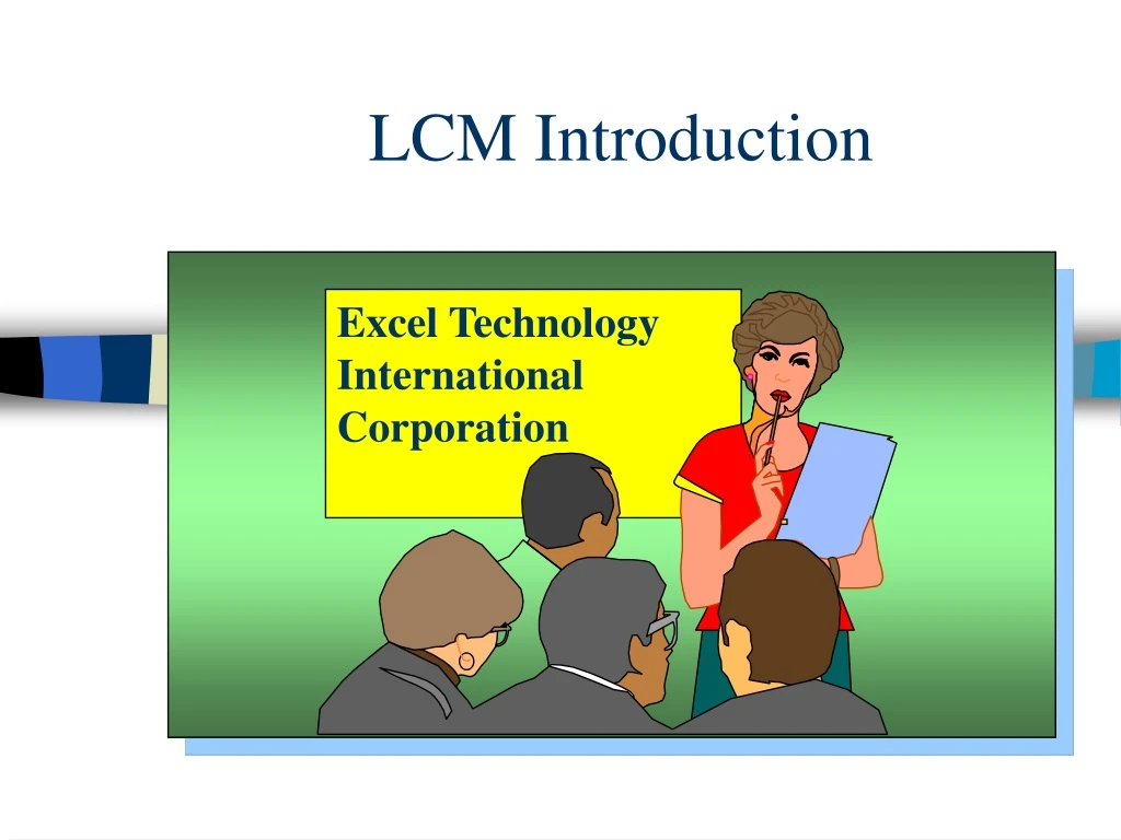
LCM Introduction Excel Technology International Corporation
LCD & LCM Differences • Liquid Crystal Display - User must decide what kind of driverto use. • LCD Module – Provides a PC Board. The driver chips are on the board ready to be used.
Construction of LCD The LCD (Liquid Crystal Display) is formed with 6~10µm thick nematic liquid crystal sandwiched between two glass plates with transparent electrode patterns, and polarizers stationed on the outside of the two glass plate. 1. Front Polarizer 2. Front Glass 3. Rear Glass 4. Rear Polarizer with Reflector 5. Sealing Glue 6. Edge Sealing Glue 7. Conductive Dot Between 2 Glass 8. ITO Electrode
Construction of LCD The LCD (Liquid Crystal Display) is formed with 6~10µm thick nematic liquid crystal sandwiched between two glass plates with transparent electrode patterns, and polarizers stationed on the outside of the two glass plate. 6. Edge Sealing Glue 8. ITO Electrode 9. Sio2 Film 10. Alignment Film 11. Spacer 12. Liquid Crystal
Top 12 O’Clock 9 O’Clock 3 O’Clock Right Left 6 O’Clock Bottom Viewing Direction
Definition of viewing angle The LCD changes in contrast depending on the direction of viewing and the range within which the display can be recognized is limited. Taking this recognizable range as the viewing angle, it is defined as below: Vertical area of definition Horizontal area of definition 1 2 Left Right Away from viewer Towards viewer
Top = 2 (12 O’Clock) Top = 2 (12 O’Clock) 2 2 1 1 Bottom = 1 (6 O’Clock) Bottom = 1 (6 O’Clock) Definition of viewing angle For TN Type LCD For STN Type LCD
Character Type Graphic Type E F H D B D B A A F I G C C Dot Size = A x B Character pitch = E Character size = H x I Size of display area = F x G Dot pitch (1) = C Dot pitch (2) = D Dot configuration and dimensions
What is a TN (Twisted Nematic) Mode LCD 90o • Twisted Nematic. • This is the abbreviation of Twisted Nematic field effect mode. This is the mode which arranges the liquid crystal molecules by controlling their movement with electric voltage (electric field) so as to twist them by 90o in the through the polarizer placed on the two upper lower plate of LCD by controlling the movement of the liquid crystal molecules. • Almost all of medium and small type segment-display LCDs are in this mode, which is therefore this is the most common mode.
What is a STN (Super Twisted Nematic) Mode LCD ? Birefringence= 120240o Super Twisted Nematic • This is the abbreviation of Super Twisted Nematic field effect mode. While the TN mode arrange the liquid crystal molecules by twisting them by 90o ,the STN mode arrange them by giving a still larger twist and provides display by birefringence effect of liquid crystal. • The LCD structure in the STN mode is the same as that in liquid crystal, adopting birefringence effect, there is a color in the display and also a background color. In this STN mode, a wide-viewing angle view is obtained, and the STN offers a high-contrast display compared with the TN mode. Specially, it is widely used in large size full-dot matrix LCD module. • For colors, it has two modes depending on the combination of polarizer, namely, yellow mode and gray mode.
Transflective Type Negative TN Mode Shutter Type Color Transmissive Type Transmissive Type D-TN Mode D-TN Color LCD Form of Display Reflective Type Colored Polarizer Transflective Type TN Mode Positive Transmissive Type Reflective Type Transflective Type Transmissive Type
Bezel (Metal Frame) PCB 1. TAB 2. COF 3. COG LCD Backlighting 1. LED 2. EL 3. C.C.F.L. Connector 1.Rubber Connector 2.Pin Connector 3.Flexible Connector LCD Driver I.C. 1. Package 2. Die Form 3. TAB Type LCM Construction
E X 1 6 2 0 0 Y F N L Y 1 B E=EL L=LED C=CCFL Series number H= High Temp. N= Normal Temp. Columns (C) x Lines (H) Display Format Character LCM LCD series No. B=Bottom view 6H T=Top view 12H A= Amber B= Blue green R= Red W= White Y= Yellow green R: Reflective F: Transflective M: Transmissive N: Negative T=TN Y= Yellow green STN G= Silver gray STN Products Numbering System Character Type
E X 2 4 1 2 8 1 Y F H L Y B E=EL L=LED C=CCFL Dot number C x R B=Bottom view 6H T=Top view 12H LCD series No. H= High Temp. N= Normal Temp. Display Format Graphic LCM A= Amber B= Blue green R= Red W= White Y= Yellow green R: Reflective F: Transflective M: Transmissive N: Negative T=TN Y= Yellow green STN G= Silver gray STN Products Numbering System Graphic Type LCM