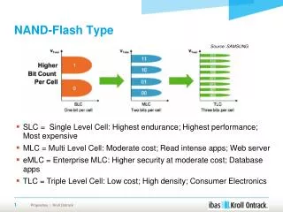
User Flash Loader For NAND flash
User Flash Loader For NAND flash. 목 차. 1. Nand Flash 구성 2. Nand Flash Source 구성과 컴파일 3. Nand Image Debugging. 1.NAND Flash 구 성. ※ Nand Flash 구성은 삼성 K9F1208UOM 을 기본으로 설명되어 있습니다 . Nand Flash 외형 및 PIN 구성. 1. NAND Flash 구 성. 2. Pin Description 1) I/O0 ~I/O7 : 데이터 버스


User Flash Loader For NAND flash
E N D
Presentation Transcript
User Flash Loader For NAND flash
목 차 1. Nand Flash 구성 2. Nand Flash Source 구성과 컴파일 3. Nand Image Debugging
1.NAND Flash 구 성 ※ Nand Flash 구성은 삼성 K9F1208UOM을 기본으로 설명되어 있습니다. • Nand Flash 외형 및 PIN 구성
1. NAND Flash 구 성 2. Pin Description 1) I/O0 ~I/O7 : 데이터 버스 2) CLE : High가 되면 현재 버스의 데이터는 명령임을 나타낸다. 3) ALE : High가 되면 현재 버스의 데이터는 주소임을 나타낸다. 4) nCE : Chip Select 5) nRE : 버스 읽기 신호 6) nWE : 버스 쓰기 신호 7) nWP : Low가 되면 쓰기나 지우기가 되지 않는다. 풀업이나 풀다운으로 연결한다. 8) R/Nb : Low가 되면 현재 작업 중임을 알리는 것이다. 풀업으로 사용한다.
1. NAND Flash 구 성 3. Arrary Fig 1
1. NAND Flash 구 성 3. Nand Flash 구성 : Nand Flash의 내부 구성도는 Fig1와 같다. Fig1을 보면 Nand Flash 메모리의 주소를 대입하여야 데이터를 읽고 쓸 수 있다. 하지만 외부와 연결된 I/O 버스는 Flash 메모리 블록과 직접 연결되어 있지 않고 여러 버퍼를 통해서 읽고 쓴다. 그래서 페이지 단위로 읽고 쓸 수 있는 구조로 구성된다. 0 Block 0 page 1st half Array (A) 256 Byte 2 page 1 Block 3 page 2 Block 2nd half Array (B) 256 Byte Spare Array (C) 8 Byte 31 page 4096 Block Fig1 Memory 구성
1. NAND Flash 구 성 3. Nand Flash 처리 순서 1) Chip Select CE신호를 Low상태로 만든다. 2) Command Nand Flash에 써넣는다. 3) Nand 내부의 접근하고자 한는 주소를 써넣는다. 4) Nand 에 데이터를 써넣거나 읽는다. 5) Nand의 상태를 감시 한다. 6) Chip Selelct인 CE 신호를 HIGH상태로 만든다. 위와 같은 방법으로 Program, Erase, Memory Read가 소프터웨어적으로 실행 한다.
2. NAND flash sources 구성과 컴파일 • 1) Nand Flash code 분석(MSM61xx ChipSet 기준) • 2) 각 소스별 수정 요소 • 3) Compile
2. NAND flash sources 구성과 컴파일 1) Nand Flash Code 분석 ① Init.s - Stack 지정 - Handler 정의 - Main Jump - Endprogram ② Buff.c - Stack Size 정의 ③ common.h - Command 정의 - Controller Register 정의 - FLASH_INFO Struck정의 - boot_info_block Struck정의 ④ NandFlash.c - Program 함수 - Erase함수(Sector, All) - InitFlash 함수 - WriteBIB 함수
2. NAND flash sources 구성과 컴파일 (1) NandFlash.c ① InitFlash Function - Nand Flash Controller Register Reset /* Reset NAND flash memory */ *cle_reg = RESET_CMD; /* Software reset the controller. */ *cle_reg = RESET_CTRL; /* Reset NAND flash memory */ *cle_reg = RESET_CMD; /* Configure NAND flash */ *flash_cfg_reg = FS_NAND_CNFG_VAL; => Reset NAND flash memory => Software reset the controller => Reset NAND flash memory => Configure NAND flash
2. NAND flash sources 구성과 컴파일 - LastAdd 지정 : Image Start Address와LastAdd가 틀리면 그 Size 만큼 0xffffffff Write한다.(Program 함수에서 수행됨) - Read Chip ID /* Do a id check. */ *cle_reg = ID_CMD; image_size = 0; LastAddr = 0; 즉. Block 1에 write를 하고 싶은 경우 LastAddr부분을 0x4000으로 수정을 해야 한다.
2. NAND flash sources 구성과 컴파일 - BIB Bad Block Check => BIB Block은 InitFlash 함수에 Define되어 있다. - Current_Block_No, Current_Page_No을 계산 한다. => Current_Block_No, Current_Page_No을 변경해서 원하는 Block에 Data를 Write할 수 있다. BIB_Block_No = 1; while(!Bad_Block_Check(BIB_Block_No) && (BIB_Block_No < BLOCK_COUNT)) BIB_Block_No++; Current_Block_No = BIB_Block_No; Current_Page_No = Current_Block_No*PAGE_CNT; BIB_Block_No가 변경이 되면 여기서 변경을 하면 됨. Ex) Block 4를 BIB Block으로 설정 할 경우 BIB_Block_No=4; BIB Block 다음 Block이 실제 Code가 들어 가는 Block이다 즉 앞에서 BIB Block을 4로 설정을 하고 나면 Code는 자동적으로 Block 5부터 Write가 된다.
2. NAND flash sources 구성과 컴파일 ※ Bad Block Check => Current_Block의 1, 2번째 Page 의 Spare Block 5번째(517) Byte를 읽어 0xff이면 Valid Block으로 0xff가 아니면 Bad Block으로 판단 한다. Bad Block 처리 부분은 사용자가 다시 설정할 수 있다. 이는 일반적으로 Nand Flash의 Bad Block Check 알고리즘에 의해서 Bad Block을 확인 하는 방법이다.(Chip Maker에서 제공) 그러나 사용자가 자기 임의 적으로 Bad Block 을 확인할 수 있다. 예) Write 후 Verify에서 Error가 발생한 경우 Bad Block으로 처리.
2. NAND flash sources 구성과 컴파일 ※ Bad Block Check Source • 1. For 문에서 Current Block의 1, • 2번째 Page의 Spare Block의 • 5번째 Byte를 읽어 확인함. • - page_address => Spare 5번째 • - *ale_reg = page_address • - *cle_reg = Spare read Comm • - spare_byte을 0xff와 비교하여 • 0xff가 아니면 Bad Block 처리함
2. NAND flash sources 구성과 컴파일 (1) NandFlash.c ② Program Function - Buff Size만큼의 Code가 USB을 통해서 RAM영역으로 Load됨 Ex) uchar Buf[BUFFER_SIZE]; => Flash_Info참조 - TargetAddr Mask 취함 => Write할 Size를 여기서 정할 수 있음.(㉠) Ex) Flash_Info.TargetAddr &= 0x3FFFFFF; - LastAddr와 TargetAddr 비교 하여 다른 경우 그 Size만큼 0xffffffff로 Write함.(㉡) - LastAddr와 TargetAddr 비교 해서 이상 없는 경우 PrepareBlock에서 Write Block Bad Check, 그리고 Erase를 함.(㉢) - Erase 후 Page 단위로 Write(Page32=512Byte)함.(㉣) - 1Page Write후 Page Count 증가, wSize(512)증가(BIB에 사용됨) Image_size증가, len감소, scP증가.(㉤) - While에서 len, Current_Block_No, Block_COUNT를 비교하여 len(Buff Size)이 0x0이 될 때까지 반복하여 수행 된다. - Write가 끝난 경우 Endprogram으로 Jump함.
2. NAND flash sources 구성과 컴파일 ㉠ ㉢ ㉣ ㉡ ㉤
2. NAND flash sources 구성과 컴파일 ※WriteChar Function ① CE 를 LOW 로 만든다.(생략) ② 플래시 메모리 읽기 명령으로 써넣을 페이지의 세부 영역을 지정한다. 처음이므로 0x00 을 써넣는다. ③ 쓰기 모드를 지정하는 명령 0x80 을 써넣는다. ④ 페이지 주소를 써넣는다. ⑤ 페이지 주소가 설정되도록 잠깐 대기한다. ⑥ 데이터를 512 바이트 써넣는다. ⑦ 플래시 메모리 쓰기 시작 명령 0x10 을 써넣는다. ⑧ 쓰기 처리가 종료되었는지 확인하기 위하여 상태 명령 0x70 을 써넣는다. ⑨ 상태 값을 읽어서 작업 중인지 확인한다. ⑩ 만약 작업 중이라면 쨄 이후 과정을 반복한다. ⑪ 종료가 되었을 때 쓰기가 되었는가를 확인한다. ⑫ CE 를 HIGH 로 만든다.(생략)
2. NAND flash sources 구성과 컴파일 ※WriteChar Function ㉠ ㉠ Data Register 512B Copy ㉡ Address, Write Register에 Command 입력 ㉢ Status Check 1 : Busy (Write 상태 임) 0 : Ready (Write가 끝난 상태임)
2. NAND flash sources 구성과 컴파일 ※OneBlockErase Function ① CE 를 LOW 로 만든다.(생략) ② 플래시 메모리 지우기 명령 0x60 을 써넣는다. ③ 블럭 주소를 써넣는다. ④ 블럭 주소 설정이 되도록 잠깐 대기한다. ⑤ 플래시 메모리 지우기 시작 명령 0xD0 을 써넣는다. ⑥ 지우기 처리가 종료되었는가를 확인하기 위해 상태 명령 0x70 을 써넣는다. ⑦ 상태 값을 읽어서 작업 중인가를 확인한다. ⑧ CE 를 HIGH 로 만든다.(생략)
2. NAND flash sources 구성과 컴파일 ※OneBlockErase Function Current Block 인자를 받아서 Block Address shift Count 계산 Erase Block Address계산 Address Register Erase Block Address 입력 Command Register에 Erase Command 입력 Erase 동안 Wait Status Check
2. NAND flash sources 구성과 컴파일 2) 각 소스별 수정 요소 (1) common.h 수정 ① Commands Define #define SEQ_DATA_CMD (uchar) 0x80 #define ID_CMD (uchar) 0x90 #define RESET_CMD (uchar) 0xFF #define READ1 (uchar) 0x00 #define READ2 (uchar) 0x50 #define PROGRAM_CMD (uchar) 0x10 #define ERASE_CMD (uchar) 0x60 #define ERASE_CONFIRM (uchar) 0xD0 #define STATUS_CMD (uchar) 0x70 ② Buffer size Define #define BUFFER_SIZE 0x80000 주의 : 위에서 Define된 Command는 Qualcomm의 MSM61xx로 설정되어 있습니다. 즉 Nand Flash제공 되는 Command와는 틀림. Non CDMA에 사용할 경우 이 부분을 수정 해야 한다.
2. NAND flash sources 구성과 컴파일 2) 각 소스별 수정 요소 (2) NandFlash.c수정 ① Page size , Block size & nand flash 관련 registers Define #define PAGE_COUNT 256 #define PAGE_CNT 32 #define PAGE_SIZE 512 #define BLOCK_COUNT 1024 #define BLOCK_SIZE 0x4000 volatile uchar *cle_reg = (uchar *)0x1A00000 ; volatile uchar *ale_reg = (uchar *)0x1900000 ; volatile ushort *data_reg = (ushort *)0x1800000 ; volatile ushort *read_busy=(ushort *)0x3000720 ; - cle_reg is Command Latch Enable Register. - ale_reg is Address Latch Enable Register. - data_reg is Data Latch Register. - read_busy is NAND flash READ/BUSY signal register. 1. BLOCK_COUNT부분을 변경 하여 Nand Flash Size를 변경할 수 있다. 주의 : 위에서 Define된 Command Registers는 Qualcomm의 MSM61xx기준으로 설정되어 있습니다.
2. NAND flash sources 구성과 컴파일 2) 각 소스별 수정 요소 (2) NandFlash.c수정 ② Start address of nand flash #define BASE_ADDR (ulong)0x01800000 ③ Setting register for protecting WatchDog reset ( Only Qualcomm processor ) //volatile ushort *AutoKick_reg = (ushort *)0x3000600; // MSM3000, 3100, 5000, 5105 //volatile ushort *AutoKick_reg = (ushort *)0x3000700; // MSM5100 //volatile ushort *AutoKick_reg = (ushort *)0x30006d0; // MSM6050, 6025 //volatile ushort *AutoKick_reg = (ushort *)0x3001080; // MSM5500 volatile ushort *AutoKick_reg = (ushort *)0x80000700; //MSM6100 //volatile ushort *AutoKick_reg = (ushort *)0x80001b40; //MSM6500 - WatchDog Reset 부분을 특정 시간 주기로 Disable 해야 한다. (Qualcomm Chipset인 경우) 사용 하는 ChipSet에 맞게 WatchDog 부분을 수정 해야 함.
2. NAND flash sources 구성과 컴파일 2) 각 소스별 수정 요소 (2) NandFlash.c수정 BIB_Block_No = 1; while(!Bad_Block_Check(BIB_Block_No) && (BIB_Block_No < BLOCK_COUNT)) BIB_Block_No++; Current_Block_No = BIB_Block_No; Current_Page_No = Current_Block_No*PAGE_CNT; - Write할 Block을 변경할 경우 FlashInit Function에서 Current_Block_No부분을 수정 해야 한다. 즉 Block4에 Write을 하고 싶은 경우 Current_Block_No = 3 이 되도록 수정 해야 한다.
2. NAND flash sources 구성과 컴파일 2) 각 소스별 수정 요소 (2) NandFlash.c수정 4) Select NAND Flash type : Samsung & Toshiba #define SAMSUNG #define TOSHIBA : 일반 적으로 Samsung, Toshiba Nand을 가장 많이 사용하고 있다. Samsung, Toshiba Nand Bad Block 처리 부분이 다르므로 사용하는 Nand Maker을 확인 하여 이 부분을 수정 하세요. 주의 : 위에서 Define된 Command Registers는 Qualcomm의 MSM61xx기준으로 설정되어 있습니다.
2. NAND flash sources 구성과 컴파일 3) Compile • Create project file ( *.mcp ) • - Please select [File]- [New] option
2. NAND flash sources 구성과 컴파일 3) Compile (2) Add source files to project : Select [Project]- [Add Files..] to add project
2. NAND flash sources 구성과 컴파일 3) Compile (3) Option setting - Assembler/Compile Select Target core & Endian setting Processor: ARM 926EJ Byte Order: Little
2. NAND flash sources 구성과 컴파일 3) Compile (4) Option setting- Linker (1) RO Base: Compile할 소스의 Start Address 설정 부분 => RAM Start Address(Target System)로 설정 해야 함.
2. NAND flash sources 구성과 컴파일 3) Compile (5) Option setting - Linker (2) Object/Symbol : Compile할 소스의 Entry Point쪽을 설정
2. NAND flash sources 구성과 컴파일 3) Compile (5) Generate Image - Select [ Project ]- [ Rebuild All ] to generate axf image file
3. NAND Image Debugging 1) Spider Option 설정 및 Download 2) 소스 Debugging
3. NAND Image Debugging 1) Spider Option 설정 및 Download(MSM61xx) (1) Debugger - SysReset Enable : Check - TRST Enable : Check - Using RTCK : Check ※ Option설정 관련 사항은 Spider Quick Start Key를 참조 하세요. 주의 : ARM926EJ Core는 RTCK을 동기 Clock으로 사용함.
3. NAND Image Debugging 1) Spider Option 설정 및 Download(MSM61xx) (2) Processor Processor Detect시 ARM926EJ Core Detect가 되는지 확인 하세요. ※ 기타 설정은 Default로 두시면 됩니다.
3. NAND Image Debugging 1) Spider Option 설정 및 Download(MSM61xx) (3) Download - File\Load Image
3. NAND Image Debugging 2) 소스 Debugging 1. Read Chip Id (3) (1) Debugging 순서 2. Flash Init (6) - Read Chip id : Nand Flash Id를 확인함. - Flash Init을 통해 BID Block Check, Write Block을 설정 한다. - Erase는 Program중 에 실행 된다. - Program이 종료 되면 BIB Block Write - End Program 3. Program (0) 4. Write BIB (5) 5. End Program
3. NAND Image Debugging 2) 소스 Debugging (2) Flash_Info Struck 구성 - Command : 0 -> Program( ) 1 -> EraseAll( ) 2 -> EraseSector( ) 3 -> ReadChipID( ) 4 -> ReadMem( ) - Result : Read ID, Erase, Program의 결과를 알 수 있음 Ex) Result : 0 => Erase, Program fail Result : 0x76ec(ec : Maker ID, 76 : Device ID) Device ID=>73:16MB, 75:32MB, 76:64MB, 79:128MB - TargetAddr : Code가 Write되는 Address(0x4000의 n승) - Length : Code가 Write되는 크기 - Buf : Write되는 Code가 들어 가는 영역
3. NAND Image Debugging 2) 소스 Debugging (3) Flash Read ID - Command 3을 준다. - Init.s소스 상에서 Endprogram에 BreakPoint설정 한다. - RUN을 하면 Result에 결과를 알 수 있다.
3. NAND Image Debugging 2) 소스 Debugging (4) Program • - Command 0을 준다 • - Init.s소스 상에서 Endprogram에 BreakPoint설정 한다. • - TargetAddr을 0x0을 준다 => LastAdd와 같아야 한다. • Length 0x200으로설정 한다.(1Page) • Buf쪽 Data를 임의의 Data로 설정 한다.(0x200 => 1Page) • RUN을 실행 한다. Program이 이상 없으면 Result가 1이 된다.
3. NAND Image Debugging ※ Write할 Data변경 • - Memory Window를 Open한다. • - Address를 Buf Address로 설정 한다. • Write할 내용을 변경 한다. => Memory function중에 Fill기능을 이용
3. NAND Image Debugging 2) 소스 Debugging (5) Read Mem => - Write한 Data를 확인 하기 위해서 Nand에 있는 Data를 Dump할 수 있다. - Command 4을 준다 - Init.s의 Endprogram에 BP설정 - Write하고 싶은 Address을 준다 => TargetAddr - Dump하고 싶은 Size를 준다. - Run을 한다 - Dump된 Data는 Buf를 통해서 확인할 수 있음.
Field Application Engineer Cho Dong Min -031-231-9926 chodm@aijisystem.com Hawng Jun Seok -031-231-9947 juns@aijisystem.com Kim Jung Han -031-231-9905 asdeer@aijisystem.com Song Seung Keun -031-231-9946 seungkeuns@aijisystem.com