A High Performance 3D Graphics Rasterizer with Effective Memory Structure
240 likes | 451 Views
A High Performance 3D Graphics Rasterizer with Effective Memory Structure. Woo-Chan Park, Kil-Whan Lee * , Seung-Gi Lee, Moon-Hee Choi, Won-Jong Lee, Cheol-Ho Jeong, Byung-Uck Kim, Woo-Nam Jung, Il-San Kim, Won-Ho Chun, Won-Suk Kim, Tack-Don Han,

A High Performance 3D Graphics Rasterizer with Effective Memory Structure
E N D
Presentation Transcript
A High Performance 3D Graphics Rasterizer with Effective Memory Structure Woo-Chan Park, Kil-Whan Lee*, Seung-Gi Lee, Moon-Hee Choi, Won-Jong Lee, Cheol-Ho Jeong, Byung-Uck Kim, Woo-Nam Jung, Il-San Kim, Won-Ho Chun, Won-Suk Kim, Tack-Don Han, Moon-Key Lee, Sung-Bong Yang, and Shin-Dug Kim Media System Lab. Yonsei University Seoul, Korea E-mail : kiwh@kurene.yonsei.ac.kr
Outline • Introduction • David Simulator • High Performance 3D Graphics Rasterizer with Effective Memory Structure (David Rasterizer) • Performance Analysis • Conclusions
NRL Project Yearly Research Plan Title Basic Environment & Research • Study Simulation Environment • 3D GA Simulator development • Survey of Related Works The Design of High Performance 3D Graphics Accelerator for Realistic Image 1st Year Technology Prevalent (15million textured polygons) Technology Prevalent 3D Graphic Accelerator Properties • Propose an Effective Architecture • Performance Evaluation • IP Co-Development 2nd Year • Institution for bringing up an • excellent lab. with a core technology • A Government-initiated Project High Performance 3D Graphic Accelerator Necessities 3rd Year High Performance (25million textured polygons) • High Performance Architecture • Building international core IP • Implementation of Prototype System • Parallel Rendering Architecture • Leadership of an advanced research • area • Synergy effect through research • interchanges ∼ 5th Year
The Design of A High Performance 3D Graphics Accelerator for Realistic Image & Building Core IPs Technology Prevalent 3D Graphics Accelerator High Performance 3D Graphics Accelerator Architecture Research • Geometry Processing Unit, Rendering Unit • Realization Mapping Unit • P-M Architecture, Memory Architecture for 3D GA • Cache & Memory Hierarchy • Parallel 3D Rendering System Design Research • Execution Model(VLIW, SIMD, RISC etc.), Control & Interface • Appliance to other system library by implementing VHDL SW Research • API & Rendering Algorithm • Geometry Compression / Modeling Verification /Integration • Construction of Simulation Environment & Verification by Simulation • Prototype System
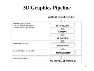
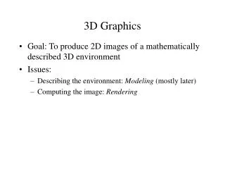
Current Research Work Vertex data(x,y,z,w) Model-view Transform ( Lighting ) Clipping Projection Divide by w Viewport Transform Triangle Setup Scan-conversion Bump map. Perspective Texture Mapping Fog / Alpha blending Z-buffering Anti-aliasing Pixel data Major Research David Simulator Arithmetic Unit • High performance floating point adder/subtractor • High performance floating point multiplier • High performance floating point divider Geometry Unit • Overlapped light geometry processing(OLGP) • New method for topological compression Rendering Unit • Object-oriented rendering using the analytic model • Effective reuse buffer for triangle mesh • Order-independent transparency • Perspective texture mapping • Efficient bump mapping • Modified anti-aliasing execution model Realization Unit Memory Unit • Texture cache simulation for various cache architectures • Texture Cache Sharing • Memory bandwidth saving scheme for texture data Related Works & Basic Research
David Simulator Simulation Work Flow Setup pipeline Texture cache Edge work pipeline Span processing Mapping unit (texture, bump, environment, displacement) Z Compare Color Blend MC for image map access MC for frame buffer access Model Data Obj format Parser OpenGL format Mesa Library Call Geometry Simulator Call FPU Instructions Rasterizer Simulator Call Geometry Engine Rasterizer Inst. & Data transfer & Store to Local memory Write data to local memory Vertex Buffer Instruction Fetch Decode Execute #1 Execute #2 Execute #3 Write Back Performance Result Performance Result
David Rasterizer Block Diagram Z-test pipeline Mapping pipeline
High Performance 3D Graphics Rasterizer with Effective Memory Structure (David Rasterizer)
Architectural features of David rasterizer • Performing z-test pipeline before TBE(Texture, Bump, and Environment) mapping completion • Saving memory bandwidth • Solve the incosistency problem with tagging scheme for pixel cache • Texture cache sharing with BE(Bump and Environment) mapping • Efficient structure
Rasterizer model : Neon, S3 Pixel information Pixel information Z read Texture cache Texture read / filter Z test Texture blend Z write Z read Texture cache Texture read / filter Z test memory memory Texture blend Alpha test Alpha test Z write Destination read Destination read Alpha blend Alpha blend Destination write Destination write Neon S3
David Rasterizer Pixel information Pixel cache Tag test and Z read Z test wide separate Texture cache Texture read / filter memory Texture blend Alpha test Tag update and Z write Destination read Pixel cache Alpha blend Destination write
Architecture Comparison Neon S3 David When is texture mapping performed? before Z test after Z test after Z test OpenGL semantics for perfectly transparent texture Support Not support Support Advantages • Support OpenGL • semantics • No wasting bandwidth • No fetching texture • data that are obscured • Simple scheme • No wasting bandwidth • No fetching texture • data that are obscured • Support OpenGL • semantics Disadvantages • Wasting bandwidth • Unable to support • OpenGL semantics • Wide separation • Inconsistency problem • Solve it using additional flag bits in a pixel cache
Texture Cache Sharing Current 3D Architecture David 3D Architecture Texture Mapping #1 Texture Mapping #1 Cache DRAM Texture Mapping #2 DRAM Shared H/W Bump Mapping Bump Mapping DRAM Shared Cache Texture Mapping #2 Environment Mapping DRAM Shared H/W Environment Mapping Current Architecture David Architecture Mapping Hardware Independent H/W Shared H/W Reduce H/W cost (about 30%) Features BE Mapping : DRAM Access BE Mapping : Cache Access Remove Pipeline Stalls due to DRAM Access Cache Size Same Same # of Read Port in Cache 2 2 Throughput 1 Cycle Texture Mapping : 1 Cycle BE Mapping : 2 Cycles (infrequent operations)
Environments for Performance Evaluation Setup pipeline Texture cache Edge work pipeline Span processing Mapping unit (texture, bump, environment, displacement) Z Compare Color Blend MC for image map access MC for frame buffer access Model Data OpenGL format Mesa Library Call Trace Generation Rasterizer Simulator Call Texture Cache Simulator Rasterizer Pixel Cache Simulator Miss Ratio, Performance Z Depth Complexity, # of Z Test Fails
Model Data SPECviewperf ProCDRS Lightscape Crystal Space (Game engine) Flarge Blocks
Bandwidth Saving in Texture Data(ProCDRS) Depth Complexity Bandwidth Saving Average 2.22 21.55%
Bandwidth Saving in Texture Data(Light) Depth Complexity Bandwidth Saving Average 2.31 29.16%
Bandwidth Saving in Texture Data(Blocks) Depth Complexity Bandwidth Saving Average 1.43 4.76%
Bandwidth Saving in Texture Data(Flarge) Depth Complexity Bandwidth Saving Average 1.31 4.93%
Conclusions • Simulation Environment (David Simulator) • Evaluation for 3D graphics accelerator architecture • Performance comparison • David Architecture • Performing z-test before TBE mapping completion • 5%~29% bandwidth savings for texture data in Scenes with 1~3 depth complexity • As the depth complexity grows, the amount of bandwidth savings become large • Recently, a 3D graphic application shows high depth complexity • Texture cache sharing with BE mapping • Hardware saving from sharing and hardware reduction for BE mappings