Download
1 / 31
310 likes | 477 Views
ISUAL Sprite Imager Electronic Design. Stewart Harris. Outline. Imager Circuit and Electronics Design Electronics Design and Fabrication Status. Imager Electronics Locations. MCP HV Supply. Front End Electronics (FEC). Phosphor HV Supply. Filter Wheel Motor. Filter Wheel Position Sensor.

E N D
ISUAL Sprite Imager Electronic Design Stewart Harris
Outline • Imager Circuit and Electronics Design • Electronics Design and Fabrication Status NCKU UCB Tohoku Sprite Imager S. Harris
Imager Electronics Locations MCP HV Supply Front End Electronics (FEC) Phosphor HV Supply Filter Wheel Motor Filter Wheel Position Sensor Daylight Sensor Electrical Board NCKU UCB Tohoku Sprite Imager S. Harris
Imager Electrical Block Diagram TEC Phosphor HVPS Intensifier J4 CCD Front End Electronics MCP HVPS J3 J2 StimLED Day-Light Sensor Imager Electrical Board Photocathode Power Supply Filter Wheel Motor Motor Driver Filter Wheel Position Sensor Heater and Thermistor Circuits not shown J1 NCKU UCB Tohoku Sprite Imager S. Harris
Imager Connector Locator J3MCP High Voltage J4Phosphor High Voltage J1Imager Electrical Board J2Front End Electronics NCKU UCB Tohoku Sprite Imager S. Harris
Image Intensifier Interface Image Intensifier - 25 mm J4 - 9 pin J3 - 9 pin MCP-Out-1kVHV Supply Phosphor (Anode -6kV) HV Supply MCP-In GND Photocathode Power Supply GATE FEC Connector Imager Electrical Board J1 - 44 pin NCKU UCB Tohoku Sprite Imager S. Harris
Imager Electrical Board Functions • Active Electronics • Photocathode Power Supply • On/off control • Gate control from FEC • Filter Wheel Motor Driver • Stepper motor (2 phases) • Position indicators (2 bits) • Connections • Thermistors • TEC hot side • Lens (front and rear) • Filter Wheel • Filter Motor • Daylight Sensor • Survival (spacecraft) • Heater Circuits • Lens (front and rear) • Filter Wheel • Survival (spacecraft) • Thermoelectric Cooler (TEC) • Power controlled from AEP • Stim Source Interface Ref Doc: 8439-A4F NCKU UCB Tohoku Sprite Imager S. Harris
Motor Controller Schematic NCKU UCB Tohoku Sprite Imager S. Harris
Photocathode Power Supply NCKU UCB Tohoku Sprite Imager S. Harris
Daylight Sensor Electronics • Specifications • Purpose: Control HV Power Supplies On/Off • Number of Channels: 2 • Sensor: 2 x UDT PIN-44DPI (per Channel) • Spectral band: 420 - 780 nm • Field of View: 2π • Threshold current: 4 nA (sum of 2 photodiodes) (1E6 photons/pixel/sec on Imager) • Range of detection: 0.1 to 1000 nA • Output: 0 to 5V NCKU UCB Tohoku Sprite Imager S. Harris
Daylight Sensor Schematic One Channel Shown Ref schematic: 8798-O9A NCKU UCB Tohoku Sprite Imager S. Harris
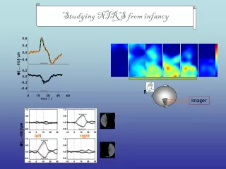
Daylight Sensor Circuit Performance NCKU UCB Tohoku Sprite Imager S. Harris
Temperature Stability - Daylight Sensor Circuit NCKU UCB Tohoku Sprite Imager S. Harris
Front End Electronics Interface Images are transferred to the AEP in data frames,each frame is 128 lines x 512 pixels • Data[0..11] • 12 bits per pixel • PixelClock (PIXCLK) • pixel data strobe • FrameValid (FRMV) • indicates duration of frame • LineValid (LINV) • indicates duration of line • used only during test • Busy (BUSY) • signals start of EXP • Acquire (ACQ) • enables modes • Event Trigger (ETRIG) • signals Spite Event • CommandData (CDI) • serial data interface for upload of camera parameters • VoltageMonitor (MON) • switched analog output • Power • dc voltages Interface Ref Doc: 8652-X7A NCKU UCB Tohoku Sprite Imager S. Harris
Front End Electronics Block Diagram J2 NCKU UCB Tohoku Sprite Imager S. Harris
CCD Bias Design NCKU UCB Tohoku Sprite Imager S. Harris
Clock Driver Design NCKU UCB Tohoku Sprite Imager S. Harris
Analog Data Chain CCD Buffer Preamp/Clamp Correlated Double Sampling (CDS) OS1 ADC RLOAD RS-422 Drivers MUX Preamp/Clamp Buffer Correlated Double Sampling (CDS) OS2 ADC RLOAD Driver Board8560-O9 Analog Processor Board8562-O9 CCD Board8559-O9 NCKU UCB Tohoku Sprite Imager S. Harris
Preamp Design NCKU UCB Tohoku Sprite Imager S. Harris
CDS Design NCKU UCB Tohoku Sprite Imager S. Harris
Digital Control NCKU UCB Tohoku Sprite Imager S. Harris
Power Supply Design NCKU UCB Tohoku Sprite Imager S. Harris
509 511 510 1 3 512 4 2 1021 513 1023 516 514 515 1024 1022 64513 65021 65023 65024 65022 64516 64514 64515 65027 65025 65533 65535 65534 65028 65026 65536 Image Readout Order CCD array is illustrated showing the order in which pixels are transferred from Imager to AEP Line 1 2 127 128 1. Each cell represents one pixel 2. Since the CCD is read from two outputs, the image is split in the middle NCKU UCB Tohoku Sprite Imager S. Harris
Data Transfer Timing Line Timing Tframe = 9.6 ms Tline = 75 s Pixel Timing Tpixel = 125 ns N > 512 NCKU UCB Tohoku Sprite Imager S. Harris
Imager Electronics Design Status • Breadboard fabrication and testing complete • Detailed design Completed • FEC Electronics Design Completed • Imager Electrical Board Design Completed • Daylight Sensor Design Completed NCKU UCB Tohoku Sprite Imager S. Harris
FEC Breadboard A breadboard version of the FEC electronics was built to test the design of clock drivers, preamps, correlated double sample (CDS) circuitry and 12-bit A/D conversion. NCKU UCB Tohoku Sprite Imager S. Harris
Breadboard Camera Measurements • Measured system gain • 29 e-/ADU • Measured readout noise • < 50 e- rms • CCD full well • ~ 120,000 e- • Dynamic range • > 2400:1 • Operating Parameters • Master clock: 22.5MHz • Pixel clock: 7.5 MHz • Line clock: 340 kHz NCKU UCB Tohoku Sprite Imager S. Harris
Breadboard Camera Image NCKU UCB Tohoku Sprite Imager S. Harris
ETU Imager Fabrication Status • Assembly of ETU Imager • FEC PC board fabrication status: • All boards assembled and tested • Imager Electrical board fabrication status: • Board etch is in process • Daylight Sensor board fabrication status: • Board is assembled and tested • Mechanical parts fabrication status: • Machining/fabrication is in process • Electrical / Electronic (EE) Parts status • see next page • Optics Parts status • see next page NCKU UCB Tohoku Sprite Imager S. Harris
EE Parts and Optics Status NCKU UCB Tohoku Sprite Imager S. Harris
The End NCKU UCB Tohoku Sprite Imager S. Harris