Download
1 / 47
470 likes | 545 Views
Explore stress measurements, fault mechanics, and wellbore stability from Chelungpu-Fault Drilling Project Meeting. Analyze stress orientations, pore pressure, and rock strength for drilling challenges.

E N D
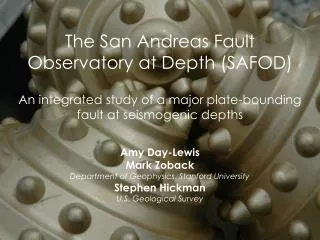
In Situ Stress Measurements, Wellbore Stability and Fault Mechanics Taiwan Chelungpu-Fault Drilling Project Meeting Mark Zoback Stanford University October 21, 2003
z 0 ( ) S z = ò r g dz v 0 0 Obtaining a Comprehensive Geomechanical Model Parameter Data Vertical stress Least principal stress Shmin LOT, XLOT, minifrac Max. Horizontal Stress SHmax magnitude modeling wellbore failures Stress Orientation Orientation of Wellbore failures Pore pressure Pp Measure, sonic, seismic Rock Strength Logs, Modeling Wellbore failure, Lab Faults/Bedding Planes Wellbore Imaging
Will There be Problems Drilling through Dipping Shales? (Shale Reaction with Mud/Stress State and Weak Bedding Planes)
What can we learn from the stress state after the earthquake? Kaj Johnson
z 0 ( ) S z = ò r g dz v 0 0 Obtaining a Comprehensive Geomechanical Model Parameter Data Vertical stress Least principal stress Shmin LOT, XLOT, minifrac Max. Horizontal Stress SHmax magnitude modeling wellbore failures Stress Orientation Orientation of Wellbore failures Pore pressure Pp Measure, sonic, seismic Rock Strength Logs, Modeling Wellbore failure, Lab Faults/Bedding Planes Wellbore Imaging
Hydraulic Fractures Propagate Perpendicular to the Least Principal Stress
z 0 ( ) S z = ò r g dz v 0 0 Obtaining a Comprehensive Geomechanical Model Parameter Data Vertical stress Least principal stress Shmin LOT, XLOT, minifrac Max. Horizontal Stress SHmax magnitude modeling wellbore failures Stress Orientation Orientation of Wellbore failures Pore pressure Pp Measure, sonic, seismic Rock Strength Logs, Modeling Wellbore failure, Lab Faults/Bedding Planes Wellbore Imaging
Stress-Induced Wellbore Failures UBI Well A FMI Well B
z 0 ( ) S z = ò r g dz v 0 0 Obtaining a Comprehensive Geomechanical Model Parameter Data Vertical stress Least principal stress Shmin LOT, XLOT, minifrac Max. Horizontal Stress SHmax magnitude modeling wellbore failures Stress Orientation Orientation of Wellbore failures Pore pressure Pp Measure, sonic, seismic Rock Strength Logs, Modeling Wellbore failure, Lab Faults/Bedding Planes Wellbore Imaging
0 0 0.25 1000 0.5 2000 0.75 3000 1.0 4000 1.25 5000 psi Unconfined Compressive Strength Horsrud (F) - #18 Coefficient of internal friction
z 0 ( ) S z = ò r g dz v 0 0 Obtaining a Comprehensive Geomechanical Model Parameter Data Vertical stress Least principal stress Shmin LOT, XLOT, minifrac Max. Horizontal Stress SHmax magnitude modeling wellbore failures Stress Orientation Orientation of Wellbore failures Pore pressure Pp Measure, sonic, seismic Rock Strength Logs, Modeling Wellbore failure, Lab Faults/Bedding Planes Wellbore Imaging
z 0 ( ) S z = ò r g dz v 0 0 Obtaining a Comprehensive Geomechanical Model Parameter Data Vertical stress Least principal stress Shmin LOT, XLOT, minifrac Max. Horizontal Stress SHmax magnitude modeling wellbore failures Stress Orientation Orientation of Wellbore failures Pore pressure Pp Measure, sonic, seismic Rock Strength Logs, Modeling Wellbore failure, Lab Faults/Bedding Planes Wellbore Imaging
KTB Stress Profile Zoback and Harjes (1997)
Central Australia Reverse/Strike Slip SHmax>>Shmin~Sv Well-27 (HDT) Well-30 (HDT) Well-54 (FMS)
Will There be Problems Drilling through Dipping Shales? (Shale Reaction with Mud/Stress State and Weak Bedding Planes)
Stable Wellbores Depend on Controlling the Width of Breakouts
if Weak bedding introduces strength anisotropy Rock mechanics test on rocks with weak planes
Side Track abandoned PG-2 Successful GIG-3 • Result • Company successfully drilled well • GIG-3 through the FB Shale • by limiting deviation to 27° and • mud weights to 10.5 ppg – 11 ppg • Company avoided costly stability • problems by following GMI’s • recommendations for this well
Modeling anisotropic breakouts in the FB shale with the given in situ stress state Anisotropic failure Anisotropic failure • Bedding plane properties: • dip = 8° (from core data) • Azi = 23° (from core data) • S0 = 4.8 MPa (from lab data) • ms = 0.21 (from lab data) Result: The in situ stress tensor derived in this study and the bedding plane properties measured in the lab can account for the anisotropic breakouts seen in the FB shale MW = 10.5 ppg MW = 12 ppg Observed Isotropic failure
Can We Use Wellbore Observations to Identify Presence of Active Faults? • Anomalous stress orientations • Anomalous stress magnitudes
Drilling-Induced Tensile FracturesRotated Near Fault at 3100 meters
Modeling Fault-Induced Stress Perturbations at the Wellbore Wall
Co-Seismic Slip Model of Chi-Chi Earthquake (GPS) Johnson and Segall (in press)
What can we learn from measuring the stress state after the earthquake? Kaj Johnson
Summary • Obtaining a Comprehensive Geomechanical Model can provide insight and help in addressing wellbore stability problems as drilling is underway and can make important contributions to the fundamental scientific objectives of the project • Engineering – Must build the model as you go – “real time” analysis with careful mud logging (cuttings analysis) • Science – Obtain critical data as project is being carried out - can’t go back and get missing data
Recommendations • Obtain logs after each phase of drilling • A complete suite of geophysical logs • Wellbore image logs are essential (both ultrasonic and electrical, if possible) • Carry out an Extended Leak Off Test (hydrofrac) each time casing is set • Carry out additional hydrofracs (if possible) – only to measure S3 • Carry out careful mud logging as drilling is underway. Laboratory tests on core samples will be important primarily for science • Make data available to science team as rapidly as possible
Most Importantly GOOD LUCK To us all!