Download
1 / 50
510 likes | 750 Views
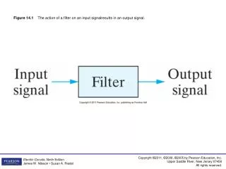
Figure 14.1 The action of a filter on an input signalresults in an output signal. Figure 14.2 A circuit with voltage input and output.

E N D
Figure 14.1 The action of a filter on an input signalresults in an output signal.
Figure 14.3 Ideal frequency response plots of the four types of filter circuits. (a) An ideal low-pass filter. (b) An ideal high-pass filter. (c) An ideal bandpass filter. (d) An ideal bandreject filter.
Figure 14.4 (a) A series RL low-pass filter. (b) The equivalent circuit at = 0 and (c) The equivalent circuit at = .
Figure 14.5 The frequency response plot for the series RL circuit in Fig. 14.4(a).
Figure 14.6 The s-domain equivalent for the circuit in Fig. 14.4(a).
Figure 14.8 The s-domain equivalent for the circuit in Fig. 14.7.
Figure 14.9 Two low-pass filters, the series RL and the series RC, together with their transfer functions and cutoff frequencies.
Figure 14.10 A series RC high-pass filter; (b) the equivalent circuit at = 0; and (c) the equivalent circuit at = .
Figure 14.11 The frequency response plot for the series RC circuit in Fig. 14.10(a).
Figure 14.12 The s-domain equivalent of the circuit in Fig. 14.10(a).
Figure 14.14 The s-domain equivalent of the circuit in Fig. 14.13.
Figure 14.16 The s-domain equivalent of the circuit in Fig. 14.15.
Figure 14.17 The magnitude plots for the unloaded RL high-pass filter of Fig 14.13 and the loaded RL high-pass filterof Fig. 14.15.
Figure 14.18 Two high-pass filters, the series RC and the series RL, together with their transfer functions andcutoff frequencies.
Figure 14.19 (a) A series RLC bandpass filter; (b) theequivalent circuit for = o ; and (c) the equivalentcircuit for = .
Figure 14.20 The frequency response plot for the\series RLC bandpass filter circuit in Fig. 14.19.
Figure 14.21 The s-domain equivalent for the circuit in Fig. 14.19(a).
Figure 14.23 The s-domain equivalent of the circuit in Fig. 14.22.
Figure 14.25 The s-domain equivalent of the circuit in Fig. 14.24.
Figure 14.26 The magnitude plots for a series RLC bandpass filter with a zero source resistance and a nonzero source resistance.
Figure 14.27 Two RLC bandpass filters, together with equations for the transfer function, center frequency, and bandwidth of each.
Figure 14.28 (a) A series RLC bandreject filter.(b) The equivalent circuit for = 0. (c) The equivalentcircuit for = .
Figure 14.29 The frequency response plot for theseries RLC bandreject filter circuit in Fig. 14.28(a).
Figure 14.30 The s-domain equivalent of the circuit in Fig. 14.28(a).
Figure 14.31 Two RLC bandreject filters, together with equations for the transfer function, center frequency, and bandwidth of each.
Figure 14.32 Tones generated by the rows and columns of telephone pushbuttons.