Download
1 / 25
250 likes | 287 Views
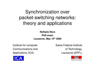
Laser synchronization and RF transmission over stabilized fibers. Russell Wilcox John Staples Larry Doolittle LCLS meeting Mar 10, 2006. Two combs can be synched by comparing two lines of each. m. m. master clock. frequency. transmitted frequencies. m - s. m - s.

E N D
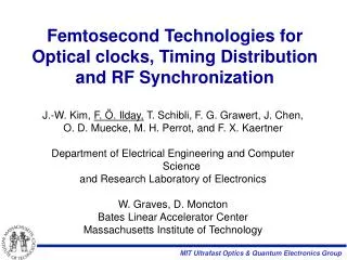
Laser synchronization and RF transmission over stabilized fibers Russell Wilcox John Staples Larry Doolittle LCLS meeting Mar 10, 2006
Two combs can be synched by comparing two lines of each m m master clock frequency transmitted frequencies m- s m- s synched laser s s m- s) - m- s) = 0 For a 1degree error in phase detection, temporal error is < 0.6fs } } m- m) - s- s) = 0 5THz 5THz
interferometer CW 1 master clock interferometer + interferometer synched laser interferometer The basic two-frequency synch scheme frep split CW 2 mux stabilized fiber demux frep
The present scheme operates at THz, but doesn’t require CEO stabilized lasers carrier/envelope offset m*frep+fceo repetition rate n*frep 0 frequency Shelton (14GHz) Bartels (456THz) Shelton et al, O.L. 27, 312 (2002) 1.4fs 1Hz-100kHz Bartels et al, O.L. 28, 663 (2003) 1.5fs 1Hz-100kHz present work (5THz) • Shelton detected only the envelope; carrier wasn’t stabilized • Bartels’ optical comparison required that the comb lines were harmonics of the reprate; carrier had to be stabilized • Present work only compares optical frequencies; carrier doesn’t have to be stabilized (only controlled to track clock)
digital mixer master clock CW 1 C2H2 digital mixer CW 2 digital mixer synched laser digital mixer Our current experimental setup 20MHz interferometer polarization controller cavity length 150fs 20MHz cross- correlator 150fs 20MHz cavity pump power 20MHz
Mixing CW with modelocked pulse trainat 100MHz l1-l2, locked to 22MHz • On a good spectrum analyser, SNR for difference frequency is 55-60dB • Better SNR of this signal results in lower phase jitter, we find 100MHz This frequency filtered, goes to phase detector 100MHz-(l1-l2), 78MHz
Noise in the modelocked fiber laser 2GHz BP Signal Analyser ML laser variable attenuator • Measured using 15GHz diode at around 1mW input power (maximizing high harmonic power, -15dBm at 2GHz) • Harmonic at 2GHz was analysed, showing 18fs RMS jitter from 1kHz to 40MHz • Results are ~2x higher than MIT laser, but power level on diode was lower, and a different diode used, so not truly comparable • A higher power diode might yield lower noise, as our result is shot noise limited at ~-156dBc
Noise in the laser lock loops amp, integrator CW laser phase detector • Both configurations tested • Based on phase detector calibration, about 250fs p-p jitter • Mainly at 650Hz and 8kHz • Need about 18x reduction in jitter • PLLs limited by oscillation • Fix: design better loop filters • Use improved lasers • Second Menlo is better • Koheras has improved design ML laser oscilloscope, FFT freq. control phase vs. time power spectrum
Measurement of modelocked laser frequency control FM demodulator ML laser network analyser • Modelocked laser reprate was frequency modulated, detected at a high harmonic (2GHz) and demodulated • Indicates several resonances at high frequencies (67kHz, 88kHz), which are also observed in the error signals of the optical phase lock loops
Menlo has improved their piezo frequency response plate piezo mirror • Piezo driven cavity end mirror controls reprate • Was a 10mm long piezo on a light Al plate • Replaced with 2mm piezo on steel plate • Control loops should be easier to stabilize • New laser will arrive soon amplitude motorized stage phase
Measurement of CW laser piezo frequency control freq. control diff. amp CW laser network analyser C2H2 cell oscilloscope • CW laser was optical frequency modulated and demodulated by tuning to edge of C2H2 absorption line. AM signal was analysed • CW laser has high frequency resonances (26kHz at +22dB, 65kHz at 32dB), also observed in its loop error signal • Overall conclusion: need to design the phase lock electronics to avoid oscillation due to excess phase from resonances • New Koheras design has better mechanical characteristics, should help
wdm wdm System issue: Brillouin scattering pump wave noise • For 2km of standard fiber, the SBS threshold is ~15mW • Larger mode area fibers exist, with higher threshold • Actual length may be ~1km, if clock is in center • We have not yet measured the jitter vs. transmitted optical power for the system, but initial tests will be <20mW per wavelength due to limited laser power • A receiver-end fiber amp might not add appreciable jitter (?) • Backscatter blockers could be placed along the fiber, with the stabilization signal at a different wavelength • Not desirable, due to added loss backward-travelling Stokes wave gain length = fiber length (for long coherence length) stabilizer wavelength transmit wavelength
System issue: phase velocity versus group velocity w1 w2 • Due to dispersion, phase and group delay are different. This would be OK, but • Due to temperature coefficient of dispersion, phase and group delays won’t change equally with temperature • For a 1km fiber, few degrees C gives ~100ps delay variation • group delay is different by 1.6% • results in 1.6ps uncorrected delay Need to fix! 1/(5THz) beat period
Phase vs. group velocicty, continued test fiber 1570nm • Three fixes • With two wavelengths transmitted, measure phase change for each, calculate correct delay change • Measure total phase delay change and add delay correction based on previous measurements • Transmit two wavelengths on two fibers, just deliver phase of each • We are currently measuring the group/phase difference • Two-frequency interferometer • RF transmission over phase-stabilized fiber • Different fibers have different coefficients 1530nm excess 1570 phase total 1530 correction
Laser synchronization transmitter • Two fibers are used, to solve group/phase velocity problem • Fibers would be in duplex cable, with common mode temperature and acoustic perturbations
Locking one 1550nm modelocked fiber laser to a 1550nm clock • Correct comb line is selected by beating user laser reprate and reference frequency • 100MHz is distributed for this and to drive frequency shifters
Locking a TiSaf modelocked laser at 800nm to a 1550nm clock • Interferometer operates at 2nd harmonic of 1550nm laser • Nonlinear fiber provides frequencies to cover gaps
Locking a Yb:KGW modelocked laser at 1048nm to a 1550nm clock • Interferes 2nd harmonic of 1048 with 3rd harmonic of 1550 • Directly diode pumped modelocked lasers are cheaper and more reliable (in principle) • Other lasers use Nd or Yb in different hosts, covering a range of wavelengths from 1030 to 1064nm • Should be able to use this technique
lock loop lock loop CW 1 clock laser line stab. pol. cont. synch laser CW 2 lock loop lock loop clok fiber loop CW fiber stabl fiber pol. cont. fiber disp. cmp loop fiber laser 3 1 3 3 1 3 5 1 4 3 1 3 In a system, everything contributes to error mux demux Assumptions: • Interferometrically stabilized main line • Thermally stabilize all other fibers to 0.01degC • Dispersion variation compensation • Low noise lasers • Uncorrelated slow noise dominates, adds in quadrature • Although, air conditioning is probably correlated • High freq. noise is filtered by limited bandwitdh control loops 2
RF transmission method • RF transmission has looser requirements on jitter • LLRF system can integrate between shots to reduce high frequency jitter
AM-to-PM conversion in a photodiode var. atten. CW laser modulator var. delay EDFA 1.1Vpp power meter network analyser • Measured at 3GHz using a network analyser • Modulation was 100% AM on 1530nm CW carrier • From 1mW to 0.5mW on a 15GHz photodiode, phase shift was 87fs/mW • In this test, phase noise from 10Hz to 3kHz was 92fs p-p. The noise was averaged over 100ms to determine AM/PM shift • CW power stability through 100m fiber <10% p-p variation over 16h (low polarization dependent loss) • This variation results in 8.7fs p-p • Conclusion: for RF transmission, AM-to-PM is not an issue
Noise in RF transmission experiment CW laser x5 x2 modulator 100MHz osc EDFA var. atten. photodiode signal analyser • Note relaxation oscillation peak around 600kHz. • Typical AM feature for fiber DFB lasers, varies between the two we have
Noise in RF transmission experiment, part 2 • When transmitted, measured “phase noise” is the same as 1GHz oscillator up to 100Hz, but limits at –130dBc/Hz above 3KHz • When baseband amplitude noise is observed on a spectrum analyser, the noise level (sideband power) is the same (scaled to 1GHz), indicating the noise is actually AM. • The E5052 shows relaxation oscillation feature of the DFB laser, (too low in AM to be converted to PM in the diode), indicating 5052 can’t tell the difference • Consistent with RIN noise and optical SNR reported in the literature* • Us: -130dBc/Hz RIN, 48dB OSNR. Them: -130dBc/Hz, 53dB • Thus the transmitter adds AM noise due to laser noise • LLRF system ignores low level AM noise • Would be common mode • LBL’s LLRF system can average phase measurement over 1ms, eliminating noise above 1kHz • Therefore, the added CW laser noise is not a system issue • This measurement indicates that an absolute measurement is misleading, so we need to do differential measurement with two receivers *IEEE Phot. Tech. Lett. 15, p.191 (2003)
An advantage of amplitude modulated CW pulse train spectrum RF out optical in f 150ps t 100MHz T two methods 3GHz 1/f • Diode has an average current limit before saturation • At saturation, high frequencies drop in power • Diode bandwidth is chosen to be equal to RF frequency, and pulse width is 1/bandwidth • For t=150ps, T=10ns and f=3GHz, AM has 15db more power in the transmitted frequency
All functions can be integrated into a system • Laser synch for any popular modelocked laser • RF transmission via modulated CW, and interferometric line stabilization • RF receiver is integrated with low level RF electronics design • All functions separated into chassis blocks for estimation of costs