Actively Stabilized Hand Held Laser Pointer May 8, 2014
250 likes | 412 Views
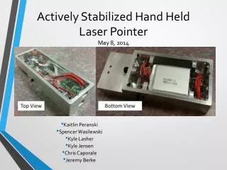
Kaitlin Peranski Spencer Wasilewski Kyle Lasher Kyle Jensen Chris Caporale Jeremy Berke. Actively Stabilized Hand Held Laser Pointer May 8, 2014. Agenda. Layout/CAD Models System Diagrams Test Bench Test Results BOM/Purchase List Future Development Technical Manual.

Actively Stabilized Hand Held Laser Pointer May 8, 2014
E N D
Presentation Transcript
Kaitlin Peranski Spencer Wasilewski Kyle Lasher Kyle Jensen Chris Caporale Jeremy Berke Actively Stabilized Hand Held Laser PointerMay 8, 2014
Agenda • Layout/CAD Models • System Diagrams • Test Bench • Test Results • BOM/Purchase List • Future Development • Technical Manual
Housing Push Button to turn on laser (Hold down to turn laser on) Turns Correction On (Forward-on) Processor USB/ Charging Port Main Power (Forward-on) NST Controller Access Charging LED (Yellow- Charging Green- Charged) Processor LED (On When Correcting)
Use Instructions • Gyroscope Calibration: • Turn module on, and leave on a stable surface until the processor led blinks. Moving the module during this process will cause the module to not calibrate properly, resulting in possible drift. • Battery Charging: • Turn module on • Plug in micro USB Cable • Yellow light on charging module will turn green when the battery is fully charged
Test Bench • Approximates a sine wave from 4 to 20 Hz • Solid state relay triggering system for solenoid actuators • Adjustable amplitude using duty cycle • Integrated gyroscope DAQ • Thermistor DAQ
Test Results • Accelerometers versus Gyroscopes • Extended Runtime • Response Time • Effectiveness using Test Bench • Effectiveness using Target • Survey
Accelerometers VS Gyroscopes Beyond 80 cm, or 31.5 in, gyroscopes begin to out sense over accelerometers.
Extended Runtime Testing Total Runtime:10.1Hours
Response Time Prototype: • The code was run for 10 seconds • The average time it took to run through the code was 1.4 ms NST Module: • The Pathways performance logger was used to determine response time to a step response • Before update – 300 ms forward, 70 ms reverse • After update – 40 ms forward, 20 ms reverse
Response Time NST Module: • While the teensy was sending commands to simulate a sine wave the performance logger was run • Response time – 3.4 ms
Effectiveness using TargetWithout Firmware Update Possible Drift** No Drift • Data Sets: • No Drift = {69.75, 20.06, 24.39, 47.06, 56.74, 44.64} • Possible Drift = {-13.95, 9.65, 36.18, 25.76, 43.98} • Extreme Drift = {-145.65} • Averages: • ND&PD&ED = 16.85% • ND&PD = 33.11% • ND = 45.60% **Drift in image is due to incorrect calibration of gyroscope
Ease of Use/Ergonomics Survey • Comments: • Module is hard to aim when the correction algorithm activated at the same time as the button press. • This led us to add a slight delay from when the button is pressed to when the correction activates • User did not know when the correction was turned on without looking at the switch • Led to us adding an LED light on the Teensy processor
Final Purchase List • Started with a $1,000 budget • Propose to spend remaining money on practical items
**These items have already been accounted for in our purchase list. Additional Items to Purchase**: • Total: $101 • Micro USB Cable • Sparkfun: $5 • Mini USB Cable • Sparkfun: $4 • Universal Laptop AC Power Adapter • Amazon: $15 • Triple Axis Digital Output Gyroscope • Sparkfun: $25 • Micro Lipo USB LiPoly Charger X 2 • Adafruit: $12 • Teensy 3.1 + Header X 2 • Adafruit: $40
Future Development • Improve Packaging • Component layout • More ergonomic • Better Quality Gyroscope • Easier calibration • Less drift • More accurate • Integration of Processors • Add gyroscope onto NST module • Use single processor • Continuous data and corrections • Reduce overall response time • Improve response of NST’s mechanical system to meet a target of 2.6 ms • Add damping to test bench • Better method to image process when using test bench • Investigate setting of limits (calibration algorithm) • Ignore any jitters below 2 Hz and focus on canceling between 2 and 20 Hz
Technical Manual • Drawing Package • Wiring Diagram • Processor Code with Notes • Current Related Patents • Use Instructions • Final BOM and Purchase List • Testing Results and Data