Download
1 / 13
150 likes | 454 Views
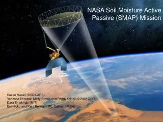
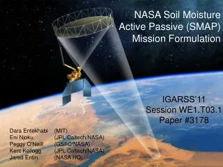
The Planned Soil Moisture Active Passive (SMAP) Mission L-Band Radar/Radiometer Instrument. Michael Spencer, Kevin Wheeler, and Samuel Chan Jet Propulsion Laboratory, California Institute of Technology Jeffrey Piepmeier, Derek Hudson and James Medeiros NASA ’ s Goddard Space Flight Center.

E N D
The Planned Soil Moisture Active Passive (SMAP) Mission L-Band Radar/Radiometer Instrument Michael Spencer, Kevin Wheeler, and Samuel Chan Jet Propulsion Laboratory, California Institute of Technology Jeffrey Piepmeier, Derek Hudson and James Medeiros NASA’s Goddard Space Flight Center IGARSS 2011, Vancouver, BC July 25-9, 2011
SMAP Science Objectives • Provide high-resolution, frequent-revisit global maps of soil moisture and freeze/thaw state to enable science and applications users to: Model Simulation of SMAP Soil Moisture & Freeze/Thaw Data • Understand processes that link the terrestrial water, energy and carbon cycles • Estimate global water and energy fluxes at the land surface • Quantify net carbon flux in boreal landscapes • Enhance weather and climate forecast skill • Develop improved flood prediction and drought monitoring capability Regions (white) are where accurate soil moisture estimates will be made (accuracy limited by dense vegetation, topography, snow/ice)
SMAP Measurement Architecture • To meet requirement for 3-day revisit time at AM local time: • 1000 km swath at 685 km dawn/dusk sun-synchronous orbit. • For wide measurement swath of combined L-Band active and passive measurement at near constant incidence angle: • Conically scanning reflector antenna. • To achieve passive resolution of 40 km and and active resolution of 3 km: • 6 meter aperture antenna • 13 rpm rotation rate • Real-aperture radiometer • Synthetic-aperture radar processing 1000 km
SMAP Mission Concept: Spatial Resolution • Radar (synthetic aperture) • Resolution pixel defined as intersection between range and Doppler “slices.” • Azimuth elongation occurs for higher radar squint angles. 28 km 36 km Swath + Altitude + Resolution • Radiometer (real aperture) • Resolution defined as root-area of elliptical footprint on surface. • Along-track spacing determined by rotation rate of antenna (30% required). 39 km 50 km (max) 28 km Antenna Diameter Rotation Rate
H and V pol signals are transmitted near-simultaneously at two different frequencies. Echoes are received simultaneously in co-pol, cross-pol and noise-only channels. Downlinked samples are processed into calibrated time-ordered single-look data. Single-look data are resampled on 1 km grid and averaged up to 3 km resolution for more precise measurements. SMAP Radar Measurement
Difference between NTE (not to exceed) allocations/requirements at L3/L4 and L2-SR requirement is “unencumbered” margin. “True” margin is that calculated against CBE’s from subsystems. This evolves with time (improved with time for Aquarius). Radar Co-Pol Radiometric Error Budget/Margins L2-SR-46: s0 accuracy of 1 dB 1-sigma (calculated for lowest s0_HH or s0_VV of -25 dB) Total Kpc Allocation: 0.8 dB L3-Instr-59 Kpr (Calibration Stability) Allocation: 0.35 L3-Instr-477: RFI Allocation: 0.4 dB Post-Launch Long-Term Calibration Allocation: 0.2 dB
SMAP Radiometer Measurement TH, TV, T3, T4 Solar radiation CMB & galactic emission Pre-launch Cal Endpoint TA TAA Lunar radiation Ionospheric Faraday rotation Atmospheric emission and absorption L1 calibration & RFI removal algorithms Post-launch Cal Endpoint L1B output TB Radio frequency interference Earth sidelobes Main beam
Key Science L2 to Core L3s L2-SR-45 : The L1B_TB brightness temperatures shall have mean uncertainty from all sources (excluding rain) of 1.3 K or less (1-sigma) in the H and V channels, computed by binning fore- and aft-look samples into 30 km x 30 km grid cells. L3-Instr-599 Long Term Drift 0.4 K L3-Instr-232 Antenna Pattern Correction : 0.6 K L3-Instr-685 Antenna Temperature Calibration 0.5 K L3-Instr-TBD Atmospheric Correction : 0.1 K L3-Instr-169 NEΔT 0.65 K L3-Instr-507 RFI 0.3 K • Difference between allocations at L3 and L2-SR performance requirement is “unencumbered” margin. • “Performance margin” carried against L4, computed using CBE’s
SMAP Instrument Concept Reflector • Antenna Subsystem • Deployable mesh antenna, boom • Shared L-Band feed horn • Radar Electronics Subsystem • Includes RF interface from despun to spun side • Radiometer Electronics Subsystem • Includes diplexers to separate radar and radiometer frequencies • Spin Subsystem • Includes BAPTA, slip rings, and RF rotary joint Feed/ OMT Deployment and Spin Motor Control V H Radiometer Electronics Diplexers RF Rotary Joint Slip Rings Spun Despun Radar Electronics C&DH Power Spacecraft
SMAP Mission Concept: Data Collection • Radiometer and radar are operated continuously in a synchronous fashion. • Radar transmits two polarizations in quick succession at approx 2850 Hz. • Radiometer samples in-between transmit events. • SAR can be commanded to two output data rates: • High rate samples for SAR imagery. • Low rate mode for real aperture data. • Radiometer can be commanded to two output data rates • High rate for RFI mitigation • Low rate for RFI quiet areas • Instrument rates commanded by S/C via look-up table in order to maximize science collection. 3 Sample SMAP Orbits High-Res Radar Radiometer (and Low-Res Radar)
Instrument Overview Radiometer is spun-side mounted to reduce losses Radar is fixed-mounted to reduce spun inertia • Radiometer • Provided by GSFC • Leverages off Aquarius radiometer design • Includes RFI mitigation (spectral filtering) • 1400-1427 MHz • Polarizations: V, H, 3rd & 4th Stokes • 1.3K accuracy • 40 km resolution • 4 Mbps data rate • Radar • Provided by JPL • Leverages off past JPL L-band science radar designs • 1MHz chirps tunable over 1217-1298 MHz • Polarizations: VV, HH, HV • 500 W SSPA (11% duty cycle) • 3 km spatial resolution • 40 Mbps data rate • Common 6m spinning Reflector • Spin Assembly and Reflector/Boom Assembly derived from heritage designs • RBA provided by NGAS-Astro • BAPTA provided by Boeing • Spun Structure & Thermal from JPL • Conically scanning at 13 rpm • Constant incidence angle of 40-deg
Instrument Development Status • Instrument subsystems in detailed design phase. • Instrument electronics engineering models in full development.