Download
1 / 40
450 likes | 1.01k Views
AVIATION HISTORY. WEEK 11. TEST REVISIONS. Basic Aircraft Parts. Fuselage / Body. Wing. Tail. Engine. Basic Aircraft Parts. Fixed (Non-Moving). Control Surfaces (Moving). Aileron for rolling Elevator for pitching Rudder for yawing. Fuselage or Aircraft Body Wing Engines Tail.

E N D
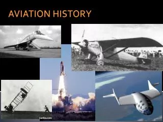
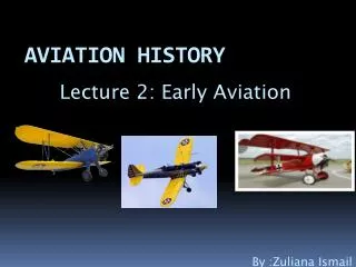
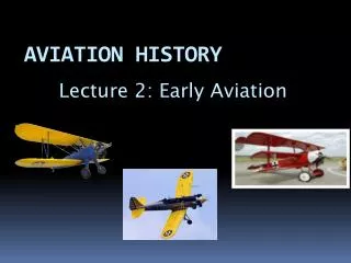
AVIATION HISTORY WEEK 11
Basic Aircraft Parts Fuselage / Body Wing Tail Engine
Basic Aircraft Parts Fixed (Non-Moving) Control Surfaces (Moving) Aileron for rolling Elevator for pitching Rudder for yawing • Fuselage or Aircraft Body • Wing • Engines • Tail
Control Surfaces Aileron
Control Surfaces Elevator Rudder
Lift High Velocity Aerofoil Low Velocity
Contents • Aviation Weather • Flying Instruments during Night and Bad Weather • Modern Technologies in aircraft Instrumentation
Introduction • History • the very first aircraft had little to no flight instruments • all weather flying was risky • navigation depended on pilot’s ability to use landmarks • The first aircraft instruments is fuel & oil pressure instruments: To warn of engine trouble so that the aircraft could be landed before engine failed).
Thunderstorms Wind Shear Icing Aviation Weather
Thunderstorms • Thunderstorms: A violent storm of thunder and lightning, often accompanied by rain and sometimes (hail) frozen rain. • Pilot is not allowed to land or take off in the face of an approaching thunderstorm. • Pilot must avoid by at least 20 miles any thunderstorm identified as dangerous
Icing • Icing is the formation of ice on parts of a aircraft (wing, engine, aircraft antenna). • Pilots and controllers need to be aware of the icing process. • Effect of the icing • Reduces aircraft efficiency: decreasing thrust & reducing lift. Aircraft become slow. • False indications on flight instruments. • Loss of radio communications, • Loss of operation of control surfaces, brakes, and landing gear.
How to avoid icing • De-icing: The process of spraying a glycol solution on the wings of an aircraft to prevent the formation of ice during inclement weather conditions. • Pilot must change altitude to get out of the icing as rapidly as possible.
Wind shear • Wind shear is a quick change in the wind speed & direction that can cause aircraft lose in control. • If an aircraft experiences a sudden decrease in wind speed, it can reduce the lift on its wings to dangerously low values. • Aircraft must be equipped with radar/ sensors that can alert pilots to wind-shear hazards.
Cross-wind • Cross-wind landing is when some amount of wind coming from the left or right of the aircraft. • If a crosswind is strong enough it can make aircraft land under bad conditions and could cause structural damage to the aircraft's undercarriage.
Flying Instrument • As airmail pilots began flying at night and in all kinds of weather in 1920’s, new instruments were developed that had enabled aircraft to fly.
VFR and IFR • VFR (Visual Flight Rules): pilot (“see and avoid”) • IFR (Instrument Flight Rules) : Pilot depends on controller (ATC)
Flying Instruments Developments • Airport Beacon • Navigational Aids System • DME,DVOR, ILS & ILS using GPS
Rotating light beacon Airport Beacons • Bonfire beacons along airmail routes (1921) • Experimental rotating light beacons (1923: Columbus-Dayton)
DVOR / DME • VOR: bearing of aircraft to radio station DVOR • (receives the signal from the VOR-ground station (waypoint) and calculates the magnetic bearing to the station • DME: distance from aircraft to radio station • VOR and DME are usually collocated, providing pilot with bearing and distance. Doppler VHF Omnidirectional Range Station (VOR) Slant range= Distance, D, is the actual distance from the aircraft to the VOR
ILS Components Marker Beacons: Needle indicates direction of runway. Centered Needle = Correct Alignment Localizer: horizontal guidance, indicates alignment w/ runway Glide Path:vertical guidance, indicates correct descent path 29
Aircraft Equipment • Approved position lights • Anti-collision light system • Weather Radar
Six Basic Instruments Airspeed Indicator Attitude Indicator Altimeter Turn Indicator Heading Indicator Vertical Speed Indicator
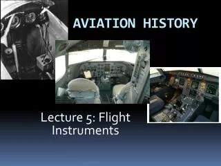
A glass cockpit is an aircraft cockpit that feature EFIS (Electronic Flight Instrument System) Uses several computer displays that can be adjusted to show flight information as needed. Glass Cockpit
Modern Technologies in aircraft Instrumentation 1. Primary Flight Display (PFD): • Displays airspeed, altitude, heading, attitude, vertical speed and yaw. • Improve a pilot's situational awareness by reducing the amount of time necessary to monitor the instruments. • Alerting the aircrew to potentially hazardous by changing the color or shape of the display or by providing audio alerts. 2. Multifunction Control Display Unit (MCDU) • Displays navigational (aircraft’s current route plan) and weather information from multiple systems (radar/ sensor)
Modern Technologies in aircraft Instrumentation 3. Electronic Centralized Aircraft Monitor (ECAM): • Shows the aircraft’s systems conditions and engines performance. • The upper ECAM screen displays engine, flaps setting, fuel quantity and alert information and is named the E/WD (Engine/Warning Display) ; • the lower ECAM displays the various systems parameters and is known as the SD (System Display). • Classic mechanical backup instruments are still provided (anemometer, artificial horizon and altimeter).
Modern Technologies in aircraft Instrumentation 4. The Flight Control Unit (FCU) • Integrates the Autopilot (AP) and Flight Director switches and communicates with the MCDU. • Autopilot (AP) - Computer device that can fly an airplane on its own. • Mostly used on long flights. However, pilot is always present to monitor and check in whether the flight is going according to plan or not.
Summary • Flight instruments all together have made • navigation easier • communication easier • fault detection and warning indication possible • takeoffs and landings easier • and most important flying safer
Question Bank • Bad whether is one of the major hazards in flying and it has also caused many accidents. List and explain three types of bad weather and explain how a pilot can avoid it. • Explain the various instruments developed that had enabled aircraft to fly at night and in bad whether. • List four flight instruments found in an aircraft cockpit to assist the pilots in flying the aircraft. • Previously, aircrafts were flown without a radio communication. What problems had this caused to the aviators? • Aircraft instruments technology is every advance now compared to two decades ago. List and explain the functions of 4 modern technologies available in aircraft instrumentation.