Mass Flow
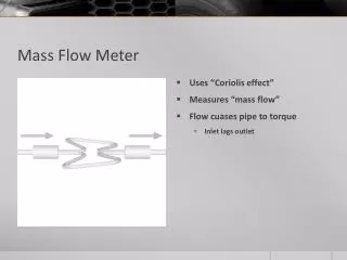
Mass Flow. Kyle Fennel Justin Hosp Omar Khan Garrett Steiger Derek Weidlein. Overview. http://www.redsealmeasurement.com/how-does-a-mass-flowmeter-work/. Coriolis flow meters are one of very few types of flow meters that directly measure mass flow rate through a pipe .


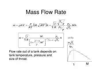
Mass Flow
E N D
Presentation Transcript
Mass Flow Kyle Fennel Justin Hosp Omar Khan Garrett Steiger Derek Weidlein
Overview http://www.redsealmeasurement.com/how-does-a-mass-flowmeter-work/ • Coriolis flow meters are one of very few types of flow meters that directly measure mass flow rate through a pipe. • The pipes in a Coriolis flow meter are vibrated by an electro-magnetic drive system, or an actuator. • The mass flow rate is calculated based on the vibration lag between the upstream and downstream ends of the meter. The lag is shown on the next slides • The density of the liquid can also be calculated based on the vibrations. The resonant frequency of the pipes is used to calculated the exact mass in the pipes at any given time, and because the pipes have a constant volume, the density can be found.
Types http://en.wikipedia.org/wiki/Mass_flow_meter http://research.che.tamu.edu/groups/Seminario/numerical-topics/mass%20flow.pdf • Coriolisflow meters are generally either composed of two parallel tubes, or one small tube within a larger tube. • In the case of two parallel tubes, the two tubes vibrate towards and away from one another. Increasing the bend and length of these tubes increases the accuracy of the flow meters • Meters with both a large and small degree of bend are depicted below, one showing vibration of empty pipes.
Types http://www3.emersonprocess.com/micromotion/tutor/39_flowoperatingprincipalSTcorflow.html http://research.che.tamu.edu/groups/Seminario/numerical-topics/mass%20flow.pdf • In the case of the concentric pipes, only the inner pipe carries fluid, while the outer pipe acts as a reference pipe. These types of Coriolis flow meters are generally not as accurate as the parallel tubes type.
Advantages http://www.bellflowsystems.co.uk/news.html • Coriolis flow meters are very accurate, within ± 0.25% error. • Because mass is measured directly, changing other conditions such as pressure or temperature does not change the calculations. • Coriolis flow meters can be used to measure flow in either direction. • Coriolis flow meters can be used to calculate mass flow rate, fluid density, and often include a thermometer. • Coriolis flow meters have very low maintenance costs compared to other flow meters due to their lack of moving parts. A mass flow meter with moving parts is depicted to the right. • Coriolis flow meters can be used for sterile processes.
Disadvantages http://www.coleparmer.com/TechLibraryArticle/667 • Coriolis flow meters are generally not accurate in measuring steam flow, or gas density. • Coriolis flow meters lose accuracy when measuring fluids with multiple phases. • Because the measurements are based on vibrations, ambient vibrations from other processes can interfere and decrease accuracy . • Coriolis flow meters may require a higher pressure drop than other methods of measuring flow rate and have a relatively low maximum operating pressure. • Coriolis flow meters can be very large, and comparatively more expensive, as shown in the table to the right.
V-velocity Ω-angular velocity Small section of the fluid that is on the inlet side away from the point of flexture at distance “r” The Coriolis force on the small fluid section δ m is δḞc =δm*ac =δm*2ΩxV Fc,Ω,V are all vectors in the above equation To simply the problem, assume the tube is a perfect U shape. Cross Section Area-A Length- L Width- d Twisting moment - Tc Tc = Fc*d= m*ac*d=ρAL*2ΩV*d A K factor can be introduced to compensate for the more generalized U-shape Tc=2KΩρAVdL=2KΩQmdL Where Qm=ρAV Measuring the Mass Flow rate of Coriolis Meter Please note that the amplitudes of the vibration and twist are extremely small compared to the size of the U-shaped tube. The above graphics are highly exaggerated for illustration purposes. http://www.efunda.com/designstandards/sensors/flowmeters/flowmeter_cor.cfm
Iu - the inertia of the U-shaped tube Cu – coefficient Ku –stiffness Θ –twist angle T- time Since the Coriolis meters are vibrating the U-shaped to generate the rotation, the real angular velocity Ω is a function of vibrating frequency ω: Assume that the damping term Cu is negligible, the equation of twisting becomes The particular solution (steady-state) solution of the twist angle is: Measuring the Mass Flow rate of Coriolis Meter http://www.efunda.com/designstandards/sensors/flowmeters/flowmeter_cor.cfm http://en.wikipedia.org/wiki/File:Coriolis_meter_vibrating_no-flow_256x256.gif
Furthermore, the velocity of the turning corners of the U-shaped tube are ΩL and the displacement difference between the 2 corners is θd/2. So the time lag is: By measuring the time lag t, the mass flow rate can be expressed as: Measuring the Mass Flow rate of Coriolis Meter http://www3.emersonprocess.com/micromotion/tutor/46_densityoptubefreq.html
Measuring the Mass Flow rate of Coriolis Meter Matlab Code for the final equation function Qm = flowrate( Ku,Iu,w,K,d,t ) %Qm - the mass flow rate of the system %Ku - stiffness coefficient given by the manufacturer % depending on the size of the Coriolis meter %Iu - the inertia of the U-shaped tube given by the manufacturer % depending on the size of the Coriolis meter %w - vibrating frequency; dependent on type of liquid flowing % through the meter %K - factor to compensate for the more generalized U-shape % this is also given by the manufacturer %d - diameter of the tube %t - time lag between the two corners Qm=(Ku-Iu*w^2)/(2*K*d^2)*t end
Orifice Meters http://www.engineeringexcelspreadsheets.com/wp-content/uploads/2011/03/Orifice-and-Venturi-Meter.jpg • An orifice meter uses differential pressure and diameter to calculate flow rate. Works similarly to a simple Venturi meter • Although they are less accurate than Coriolis meters, DP orifice meters can withstand higher temperatures • Pressure is measured at the before and after the orifice, and the diameters of your orifice plates, D1 and D2, are known • A probe measures the temperature of the fluid, which is used to calculate the fluid density • P1, P2, D1, D2, and ρ are substituted into a modified Bernoulli’s equation to solve for the mass flow rate of the fluid
Mass Flow Calculations for Orifice Meter Definition of variables - mass flow rate A – cross sectional area Di – diameter at first orifice plate D0– diameter at second orifice plate – density of fluid i – average velocity of fluid at Di 0 – average velocity of fluid at D0 – pressure drop P1-P2 Important Relationships • (use in substitutions) http://www.efunda.com/formulae/fluids/images/DP_OrificePlate_cal.gif Calculations Bernoulli’s Equation with pressure and kinetic energy terms Substitute for Factor out Solve for
Using Matlab to Calculate Mass Flow functiondporificemeter(D1,D2,P1,P2,rho) %Inputs %D1 = larger diameter (m) %D2 = smaller diameter (m) %P1 = pressure at D1 (Pa) %P2 = pressure at D2 (Pa) %rho = fluid density (kg/m^3) % %Output %Qm = mass flow rate (kg/s) if D1<=D2 error('The second orifice plate should have a smaller diameter') elseif P2>=P1 error('Pressure should drop from P1 to P2') else Qm = sqrt(((P1-P2)*pi^2*rho)/(8*((1/D2^4)-(1/D1^4)))) end
Turbine Meters http://www.globalspec.com/ImageRepository/LearnMore/20129/Turbine2c3d99fe6296b4920b1d692bc121a21a2.gif • In order to calculate flow, a turbine meter uses a sensor to calculate the rate of rotation of the turbine blades • The measured spin frequency is related to the fluid flow in the pipe by a K-factor • Each turbine has a unique K value that will need to be calibrated • At high flow rates K is relatively constant and will yield accurate flow rate results. At low flow rates, fluid friction on the turbine makes results inaccurate. • If the turbine meter has been calibrated and there is a large flow rate, flow rate can be calculated as:
Turndown Ratio http://research.che.tamu.edu/groups/Seminario/index-1.html • Compare the range of flow measuring devices • The ratio of top-end to low-end flow rates • Indicates the range in which flow meter can accurately measure the fluid qmax = maximum flow rate, qmin = minimum flow rate • Large turndown ratios beneficial to • Batch reactors • Multiproduct financial transfer • Process startup applications
Turndown Ratio • Technique to determine turndown ratio: • Minimum accuracy is defined, to set low-end flow rate • Zero Stability – limits within which the meter zero may drift during operation and is constant over the operating range • Percentage of nominal mass flow or value of flow rate units • Limiting factor when establishing turndown ratio • Achievable when the Coriolis meter is installed and re-zeroed at operating conditions • Coriolis meter must be zeroed at normal process temperature conditions, due to zero stability dependence on temperature
Turndown Ratio 2.Maximum pressure is defined, to determine top-end flow rate
Turndown Ratio function [ Qvb ] = Untitled( Pag,pfr,Prg,pfa,Qvf,pfa,pba ) %Pag = differential pressure across coriolis meter with application gas %pfr = density of reference gas at flowing conditions %Prg = differential pressure across coriolis meter with reference gas %pfa = density of application gas at flowing conditions %Qvf = volume flow rate of reference gas at flowing conditions %pfa = density of application gas at base conditions %pba = volume flow rate of application gas at bas conditions Qvb = [sqrt((Pag*pfr)/(Prg*pfa))*Qvf*pfa]/pba end
Pressure drop is proportional to the flowrate squared. High Flowrates result in higher pressure drops but greater accuracies. At lower flowrates (high turndown), pressure drop is lower, but accuracy is lower as well. http://www.documentation.emersonprocess.com/groups/public_public_mmisami/documents/articles_articlesreprints/jds-030705naturalgas.pdf
Prices of Coriolis Meters VS. Other Flow Measurement Devices (Flo-Corp,2013) • It is true that the capital costs of Coriolis meters are higher than that of other Flow meters. • However it is worth mentioning that their maintenance costs are minimum since they have such few parts. (Stappert)
Prices of a few Coriolis Meters Name: DMF- series Micro Coriolis Flow Meter Price: US $200 – 5000/unit ( Depending on Size and Weight) Company: Beijing Automation Equipment Co.Ltd Name: Coriolis Mass Flow Meter Price: US $1000 – 20,000 / set Company: Liaoning MEC Group Co.Ltd (Ali-baba Showroom)
This table compares the capital costs of a 1 in. diameter Coriolis, Orifice, and Turbine meters over a 10-year span Capital Costs
This gives a visual representation of the difference in costs of a 1 in. diameter Low end Coriolis, High end Coriolis, Orifice, and Turbine meters over a 10-year span http://research.che.tamu.edu/groups/Seminario/numerical-topics/mass%20flow.pdf Capital Costs
A Wise Investment? • Though at the end of the day the initial price of buying Coriolis meters may be great, it justifies its cost in the long run • Provides much more accurate readings than its competitors • No need for a field operator since it unlike its competitors, it automatically accounts for Pressure and Temperature. (O’Bannon,2013)
Conclusion • In conclusion, Coriolis meters measure mass flow rate extremely accurately for a large range of fluids and volume flow rates. While they are more expensive to start up than conventional flow measurement devices, they are much more cost efficient in the long run after maintenance and additional costs are considered. • Future work could include making Coriolis meters more accurate over a wider range of flow rates, finding ways to make them smaller and lighter with different materials and further compare parallel and concentric type Coriolis meters.
References • http://www.engineeringexcelspreadsheets.com/wp-content/uploads/2011/03/Orifice-and-Venturi-Meter.jpghttp://www.ematem.org/Dokumente/2008_lau_calculat.pdf • http://www.documentation.emersonprocess.com/groups/public_public_mmisami/documents/articles_articlesreprints/jds-030705naturalgas.pdf • http://www.efunda.com/designstandards/sensors/flowmeters/flowmeter_cor.cfm • http://www.efunda.com/formulae/fluids/images/DP_OrificePlate_cal.gif • http://www.globalspec.com/ImageRepository/LearnMore/20129/Turbine2c3d99fe6296b4920b1d692bc121a21a2.gif • http://www.efunda.com/designstandards/sensors/flowmeters/flowmeter_cor.cfm • http://www3.emersonprocess.com/micromotion/tutor/46_densityoptubefreq.html • "Showroom Measurement & Analysis Instruments Flow Measuring Instruments Flow Meters Coriolis Flow Meter: 1,561 Products Found from 53 Suppliers Manufacturers." Coriolis Flow Meter, Coriolis Flow Meter Products, Coriolis Flow Meter Suppliers and Manufacturers at Alibaba.com. N.p., n.d. Web. 27 Nov. 2013. <http://www.alibaba.com/showroom/coriolis-flow-meter.html>. • Bannon, Tom O. "Coriolis: The Direct Approach to Mass Flow Measurement." Back to Basics (2013): 41-46. Print. • "FLO-CORP: Choosing The Correct Flow Meters For Hydraulic Fracturing." FLO-CORP: Choosing The Correct Flow Meters For Hydraulic Fracturing. N.p., 25 July 2013. Web. 27 Nov. 2013. <http://flowlineoptions.blogspot.com/2013/07/choosing-correct-flow-meters-for.html>. • Stappert, Karl. "Coriolis Mass Flow Meters For Natural Gas Measurements." (n.d.): n. pag. Print. • http://en.wikipedia.org/wiki/File:Coriolis_meter_vibrating_no-flow_256x256.gif