Download
1 / 30
300 likes | 505 Views
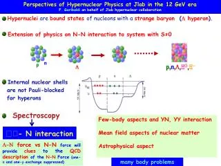
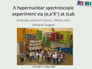
Λ hypernuclear spectroscopic experiment via ( e,e’K + ) at JLab. Graduate school of science , Tohoku Univ. Toshiyuki Gogami. JLab Hall-C in May 2009. Contents. ( e,e’K + ) experiment Introduction of JLab E05-115 Development for high multiplicity data. ( e,e’K + ) reaction experiment.

E N D
Λ hypernuclear spectroscopic experiment via (e,e’K+) at JLab Graduate school of science , Tohoku Univ. Toshiyuki Gogami JLab Hall-C in May 2009
Contents • (e,e’K+) experiment • Introduction of JLab E05-115 • Development for high multiplicity data
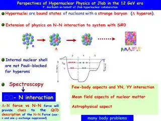
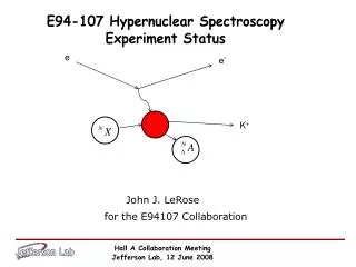
Spectroscopic experiment via (e,e’K+) reaction e + p➝ e’ + K+ + Λ Feynman diagram e- e e u u γ* K+ – γ* u s p d s p K+ u Λ Λ d n target nucleus measure Missing mass : M2HY = (Ee + MT - EK+ - Ee’)2 - ( pe - pK+- pe’)2 • Binding energy • Cross section
(e,e’K+) reaction (e,e’K+) (π+ , K+) (K- , π-) e + p➝ e + K+ + Λ π+ + n➝ K+ + Λ K- + n➝ π- + Λ e e – – u u u u Reaction K+ π+ – – K- π- s s d u d u γ* K+ – u s p d s d s d s n d d n d d u Λ Λ Λ u u u u d Momentum transfer (Typical ) ~300 [MeV/c] ~300 [MeV/c] ~90 [MeV/c] Λ can be bounded in deeper orbit Λ’s Spin At forward angle flip ≈ non-flip non-flip non-flip Spin dependent structure proton neutron neutron Λ’s from Mirror lambda hypernuclei primary secondary secondary Beam High quality , high intensity Target Thin (~100 mg/cm2) (Isotopically enriched) Thick(> a few [g/cm2] ) Thick(> a few [g/cm2] ) Energy resolution (FWHM) ≤ 500 [keV] 1 – 3 [MeV] 1 – 3 [MeV] Fine structure
JLab CEBAF ( Continuance Electron Beam Accelerator Facility ) • Requirement for accelerator • high duty factor • high intensity • smallemittance • small ΔE/E • (e,e’K+) experiment • Coincidence experiment (K+ and e-) • Small cross section ( ~100 [nb/sr] ) 1/1000 • Energy resolution sub MeV (FWHM) CEBAF can satisfy these requirements Thomas Jefferson National Accelerator Facility 22nd Indian-summer school (SNP2010) 100 [m]
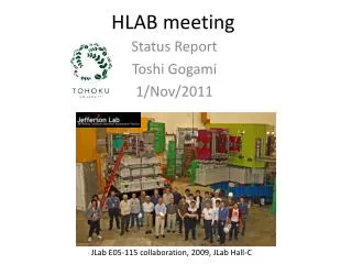
(e,e’K+) experiment in JLab Hall-C 2000年 1st generation exp.JLab E89-009 ENGE(e’) + SOS(K+) 12ΛB ~ 900 [keV] (FWHM) Proof of feasibility 2005年 2nd generation exp.JLab E01-011 ENGE(e’) + HKS(K+) + Tilt method 7ΛHe,12ΛB,28ΛAl ~ 500 [keV] (FWHM) Establish exp. method Luminosity ×137 e’ rate 1/200 S/N ×2.7 2009年 3rd generation exp.JLab E05-115 HES(e’) + HKS(K+) + Tilt method 7ΛHe,9ΛLi,10ΛBe,12ΛB,52ΛV ≤ 500 [keV] (FWHM) Medium heavy Strangeness 2010 at KEK
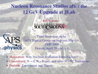
E05-115 experimental motivation (1) • 2009 Aug – Nov @ JLab Hall-C • (e,e’K+) reaction • Target : 7Li , 9Be , 10B , 12C , 52Cr First try It is difficult experimentally. “ b.g. electron due to brems. ∝ ~Z2 “ • p-shell(7He , 9Li , 10Be , 12B) • Charge symmetry breaking (CSB) • ΛN-ΣN coupling Λ Λ Λ Λ BΛ[MeV] • Medium heavy (52V) • s-,p-,d-,f-orbit binding energy & cross section • Mass dependence of Λ single particle energy • l・s splitting,core configuration mixing • dΛ, fΛ –state Λ A = 52
JLab E05-115 experimental setup e + p → e’ + Λ + K+ 7Li , 9Be , 10B , 12C , 52Cr 2×10⁻⁴ 7 [msr] 3 – 12 [deg] 2×10⁻⁴ 11 [msr] 2 – 12 [deg]
JLab E05-115 experimental setup e + p → e’ + Λ + K+ 7Li , 9Be , 10B , 12C , 52Cr 2×10⁻⁴ 7 [msr] 3 – 12 [deg] 2×10⁻⁴ 11 [msr] 2 – 12 [deg]
HKS detectors June 2009 in JLab Hall-C 1 [m] • HKS trigger • CP = 1X ×1Y × 2X • K = WC ×AC • CP × K − π+ K+ p ~18 [kHz] (8 [μA] on 52Cr) K+ p, π+ Drift chambers -KDC1,KDC2- • Cherenkov detectors -AC,WC- • Aerogel (n=1.05) • Water (n=1.33) TOF walls -2X,1Y,1X- (Plastic scintillators) σ ≈ 200 [μm] TOF σ ≈ 170 [ps]
HES Detectors HES D magnet Drift chambers - EDC1 , EDC2 - TOF walls - EH1 , EH2 - (Plastic scintillators) σ ~ 300 [ps] Time Of Flight HES trigger EH1 ×EH2 ~2 [MHz] (8 [μA] on 52Cr) e Strangeness 2010 at KEK
Data Summary JLab E05-115 (2009/June – 2009/Nov)
Analysis process HES This talk HKS tracking tracking x , x’ , y , y’ at Reference plane x , x’ , y , y’ at Reference plane F2T function F2T function x’ , y’ , p at Target x’ , y’ , p at Target particle ID (select K+) Missing Mass tune tune p : Λ , Σ0 ,12ΛB Angle : Sieve slit
Λ and Σ0 p(γ*,K+)Λ,Σ0 ~40 hours (5 shifts) Because of high multiplicity of HKS (analysis code cannot handle with high multiplicity)
Analysis for high multiplicity data KDC2 KDC1 HKS event display
Background event of HKS Overhead view 9Be , 38.4 [μA] KDC1 Background events x [cm] Β ≈ 1 e- , e+ KDC2 Events on HKS optics y [cm] KDC1 KDC2 z [cm] HKS dipole magnet NMR port SIMULATION
Singles rate summary HKS Up to ~30 [MHz] HKS trigger ~ 10[kHz] HES Up to ~15 [MHz] COIN 2.0 [kHz] HES trigger ~ a few[MHz]
Multiplicity of typical layer of chamber HES HKS ~1.13 ~2.24 ~4.94 ~1.28 Multiplicity is high for HKS
Hit wires in KDC1 KDC1 Overhead view Overhead view Misidentification chance in hit wires selection increase ! low high low high REAL DATA REAL DATA Black : hit wires Blue : selected wires Red : track Black : hit wires Blue : selected wires Red : track CH2 52Cr
New tracking scheme NEW • Hit wire selection with TOF • 1X & 2X • Grouping • Pre-PID • Cherenkov detectors Good TDC High multiplicity Pattern recognition Reduce hit wires to analyze Solve left right Select good combination Combination selection with TOF counters Reduce hit wire combinations (h_tof_pre.f) Track fit
DC hit info. selection with TOF Gravity CUT Particle direction ~17% Selective region Maximum gradient ~8% CUT Minimum gradient Procedure in “h_dc_tofcut.f” Get KTOF1X & 2X hit counter information Make combination of 1X and 2X hit counter if those two are in same group (grouping) Determine cut conditions on KDC1 & KDC2 Select Hit wires in KDC and Reorder them
Hit wires event display (1) Gravity • GREEN region Selective region • RED markers Selected hit wires • BLACK markers Rejected hit wires Particle direction Seems to work well
Apply to u,v-layer v v’-layer Selective region determined by 1X and 2X Applied to uu’ and vv’ layers , too. Convert xx’-layer
Hit wires event display (2) KDC1 KDC2 v v’ v v’ uu’ uu’ • GREEN regionSelective region • RED markers & linesSelected hit wires • BLACK markers & lines Rejected hit wires particle particle x x’ x x’
Results of Introduction new code CH2 Λ c.s. (CH2/H2O) issue is solved Increased ! 52Cr Increased !
Summary and Outlook • 3rd generation exp. E05-115 at JLab Hall-C in 2009 • 7ΛHe, 9ΛLi, 10ΛBe, 12ΛB, 52ΛV • Analysis for high multiplicity data • Developed new tracking code Analysis efficiency is improved ! (number of event) Λ cross section of H2O and CH2 are consistent • To get better energy resolution • Fine parameter optimization • Matrix tuning