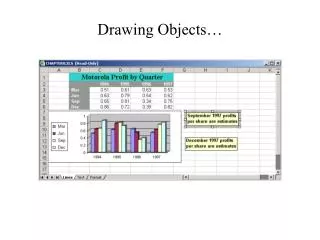
Drawing Objects
Drawing Objects . Introduction. The Draw commands can be used to create new objects such as lines and circles. Most AutoCAD drawings are composed purely and simply from these basic components. A good understanding of the Draw commands is fundamental to the efficient use of AutoCAD.

Drawing Objects
E N D
Presentation Transcript
Introduction • The Draw commands can be used to create new objects such as lines and circles. Most AutoCAD drawings are composed purely and simply from these basic components. A good understanding of the Draw commands is fundamental to the efficient use of AutoCAD. • The sections to follow cover the most frequently used Draw commands such as Line, Polyline and Circle as well as the more advanced commands like Multiline and Multiline Style.
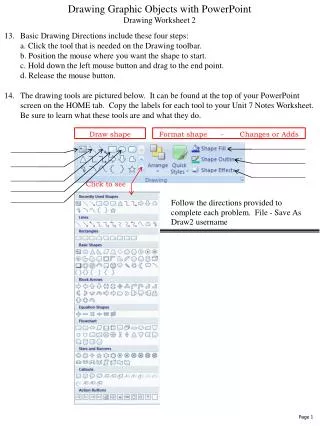
In common with most AutoCAD commands, the Draw commands can be started in a number of ways. Command names or short-cuts can be entered at the keyboard, commands can be started from the Draw pull-down menu, shown on the right or from the Draw toolbar. • If you are working with the pull-down menus, it is worth considering the visual syntax that is common to all pull-downs used in the Windows operating system. For example, a small arrow like so " " next to a menu item means that the item leads to a sub-menu that may contain other commands or command options. An ellipses, "…" after a menu item means that the item displays a dialogue box.
Lines • Lines are probably the most simple of AutoCAD objects. Using the Line command, a line can be drawn between any two points picked within the drawing area. Lines are usually the first objects you will want to draw when starting a new drawing because they can be used as "construction lines" upon which the rest of your drawing will be based. Never forget that creating drawings with AutoCAD is not so dissimilar from creating drawings on a drawing board. Many of the basic drawing methods are the same. • Anyone familiar with mathematics will know that lines drawn between points are often called vectors. This terminology is used to describe the type of drawings that AutoCAD creates. AutoCAD drawings are generically referred to as "vector drawings". Vector drawings are extremely useful where precision is the most important criterion because they retain their accuracy irrespective of scale
The Line Command • With the Line command you can draw a simple line from one point to another. When you pick the first point and move the cross-hairs to the location of the second point you will see a rubber band line which shows you where the line will be drawn when the second point is picked. Line objects have two ends (the first point and the last point). You can continue picking points and AutoCAD will draw a straight line between each picked point and the previous point. Each line segment drawn is a separate object and can be moved or erased as required. To end this command, just hit the enter key on the keyboard. • Toolbar: • Pull-down: Draw Line • Keyboard: LINE short-cut: L
You can also draw lines by entering the co-ordinates of their end points at the command prompt rather than picking their position from the screen. This enables you to draw lines that are off screen, should you want to. Command SequenceCommand: LINEFrom point: (pick P1)To point: (pick P2)To point: (to end) The Line Command, cont.
The Construction Line command creates a line of infinite length which passes through two picked points. Construction lines are very useful for creating construction frameworks or grids within which to design. Construction lines are not normally used as objects in finished drawings, it is usual, therefore, to draw all your construction lines on a separate layer which will be turned off or frozen prior to printing. Because of their nature, the Zoom Extents command option ignores construction lines. Toolbar: Pull-down: Draw Construction Line Keyboard: XLINE short-cut: XL The Construction Line Command
The Construction Line Command, cont. • Command SequenceCommand: XLINEHor/Ver/Ang/Bisect/Offset/<From point>: (pick a point)Through point: (pick a second point)Through point: (to end or pick another point)
You may notice that there are a number of options with this command. For example, the "Hor" and "Ver" options can be used to draw construction lines that are truly horizontal or vertical. In both these cases, only a single pick point is required because the direction of the line is predetermined. To use a command option, simply enter the capitalized part of the option name at the command prompt. Follow the command sequence to the right to see how you would draw a construction line using the Horizontal option. Command SequenceCommand: XLINEHor/Ver/Ang/Bisect/Offset/<From point>: H Through point: (pick a point to position the line) Through point: (to end or pick a point for another horizontal line) The Construction Line Command, cont.
Toolbar: custom Pull-down: Draw Ray Keyboard: RAY The Ray command creates a line similar to a construction line except that it extends infinitely in one direction from the first pick point. The direction of the Ray is determined by the position of the second pick point. Command SequenceCommand: RAY From point: (pick the start point) Through point: (pick a second point to determine direction) Through point: (to end or pick another point) The Ray Command
The Polyline Family • Polylines differ from lines in that they are more complex objects. A single polyline can be composed of a number of straight-line or arc segments. Polylines can also be given line widths to make them appear solid. The illustrations below show a number of polylines to give you an idea of the flexibility of this type of line.
The Polyline Quandary • You may be wondering, if Polylines are so useful, why bother using ordinary lines at all? There are a number of answers to this question. The most frequently given answer is that because of their complexity, polylines use up more disk space than the equivalent line. As it is desirable to keep file sizes as small as possible, it is a good idea to use lines rather than polylines unless you have a particular requirement. You will also find, as you work with AutoCAD that lines and polylines are operationally different. Sometimes it is easier to work with polylines for certain tasks and at other times lines are best. You will quickly learn the pros and cons of these two sorts of line when you begin drawing with AutoCAD.
The Polyline Command • Toolbar • Pull-down: Draw Polyline • Keyboard: PLINE short-cut: PL
The Polyline Command • The Polyline or Pline command is similar to the line command except that the resulting object may be composed of a number of segments which form a single object. In addition to the two ends a polyline is said to have vertices (singular vertex) where intermediate line segments join. In practice the Polyline command works in the same way as the Line command allowing you to pick as many points as you like. Again, just hit to end. As with the Line command, you also have the option to automatically close a polyline end to end. To do this, type C to use the close option instead of hitting . Follow the command sequence below to see how this works.
Polyline Command • Command SequenceCommand: PLINE From point: (pick P1) Current line-width is 0.0000Arc/Close/Halfwidth/Length/Undo/Width/<Endpoint of line>: (pick P2) Arc/Close/Halfwidth/Length/Undo/Width/<Endpoint of line>: (pick P3) Arc/Close/Halfwidth/Length/Undo/Width/<Endpoint of line>: (pick P4) Arc/Close/Halfwidth/Length/Undo/Width/<Endpoint of line>: (pick P5) Arc/Close/Halfwidth/Length/Undo/Width/<Endpoint of line>: (or C to close)
Polylines • In the illustration on the right, the figure on the left was created by hitting the key after the fifth point was picked. The figure on the right demonstrates the effect of using the Close option.
Polyline editing • It is worth while taking some time to familiarize yourself with the Polyline command as it is an extremely useful command to know. Try experimenting with options such as Arc and Width and see if you can create polylines like the ones in the illustration above. The Undo option is particularly useful. This allows you to unpick polyline vertices, one at a time so that you can easily correct mistakes. • Polylines can be edited after they are created to, for example, change their width. You can do this using the PEDIT command, Modify Object Polyline from the pull-down menu.
The Rectangle Command • Toolbar • Pull-down: Draw Rectangle • Keyboard:RECTANGLE short-cuts: REC or RECTANG • The Rectangle command is used to draw a rectangle whose sides are vertical and horizontal. The position and size of the rectangle are defined by picking two diagonal corners. The rectangle isn't really an AutoCAD object at all. It is, in fact, just a closed polyline which is automatically drawn for you.
Rectangle command, cont. • Command SequenceCommand: RECTANGChamfer/Elevation/Fillet/Thickness/Width/<First corner>: (pick P1)Other corner: (pick P2) • The Rectangle command also has a number of options. Width works in the same way as for the Polyline command.
The Polygon Command • The Polygon command can be used to draw any regular polygon from 3 sides up to 1024 sides. This command requires four inputs from the user, the number of sides, a pick point for the centre of the polygon, whether you want the polygon inscribed or circumscribed and then a pick point which determines both the radius of this imaginary circle and the orientation of the polygon. The polygon command creates a closed polyline in the shape of the required polygon. • This command also allows you to define the polygon by entering the length of a side using the Edge option. You can also control the size of the polygon by entering an exact radius for the circle. Follow the command sequence below to see how this command works.
Toolbar Pull-down: Draw Polygon Keyboard:POLYGON short-cut: POL Command SequenceCommand: POLYGONNumber of sides <4>: 5 Edge/<Center of polygon>: (pick P1 or type E to define by edge length)Inscribed in circle/Circumscribed about circle (I/C) <I>: (to accept the inscribed default or type C for circumscribed) Radius of circle: (pick P2 or enter exact radius) Polygon Command, cont.
Polygon Command, cont. • In the illustration above, the polygon on the left is inscribed (inside the circle with the polygon vertexes touching it), the one in the middle is circumscribed (outside the circle with the polyline edges tangential to it) and the one on the right is defined by the length of an edge.
Toolbar: custom Pull-down: Draw Donut Keyboard: DONUT short-cut: DO This command draws a solid donut shape. AutoCAD asks you to define the inside diameter i.e. the diameter of the hole and then the outside diameter of the donut. The donut is then drawn in outline and you are asked to pick the centre point in order to position the donut. You can continue picking centre points to draw more donuts or you can hit to end the command. Surprisingly, donuts are constructed from single closed polylines composed of two arc segments which have been given a width. Fortunately AutoCAD works all this out for you, so all you see is a donut. The Donut Command
Donut Command Sequence • Command: DONUTInside diameter <0.5000>: (pick any two points to define a diameter or enter the exact length)Outside diameter <1.0000>: (pick any two points to define a diameter or enter the exact length)Center of doughnut: (pick P1)Center of doughnut: (to end or continue to pick for more doughnuts)
Donut Command Sequence, cont. • As an alternative to picking two points or entering a value for the diameters, you could just hit to accept the default value. Most AutoCAD commands that require user input have default values. They always appear in triangular brackets like this <default value>.
Circles, Arcs etc. • Along with Line and Polyline, the Circle command is probably one of the most frequently used. Fortunately it is also one of the simplest. However, in common with the other commands in this section there are a number of options that can help you construct just the circle you need. Most of these options are self explanatory but in some cases it can be quite confusing. The Circle command, for example, offers 6 ways to create a circle, while the Arc command offers 10 different methods for drawing an arc. The sections to follow concentrate mainly on the default options but it is okay to experiment.
The Circle command is used to draw circles. There are a number of ways you can define the circle. The default method is to pick the centre point and then to either pick a second point on the circumference of the circle or enter the circle radius at the keyboard. Toolbar Pull-down: Draw Circle Center, Radius Keyboard: CIRCLE short-cut: C The Circle Command
Circle Command Sequence • Command: CIRCLE3P/2P/TTR/<Center point>: (pick P1)Diameter/<Radius>: (pick P2 or enter the exact radius)
Circle • As you can see from the command prompt above the default options are always indicated in triangular brackets like so <Default> and each option is separated by a forward slash like this /. You can choose to use the alternative options by typing them at the prompt. For example, the circle command gives you three extra options to define a circle. 3P which uses any three points on the circumference, 2P which uses two points on the circumference to form a diameter and TTR which stands for Tangent Tangent Radius. Obviously to use this last option you need to have drawn two lines which you can use as tangents to the circle. Try these options out to see how they work. There are two more circle options on the pull-down menu that enable you to draw a circle by defining the center and diameter or by using 3 tangents.
The Arc Command • The Arc command allows you to draw an arc of a circle. There are numerous ways to define an arc, the default method uses three pick points, a start point, a second point and an end point. Using this method, the drawn arc will start at the first pick point, pass through the second point and end at the third point. Once you have mastered the default method try some of the others. You may, for example need to draw an arc with a specific radius. All of the Arc command options are available from the pull-down menu.
Toolbar Pull-down: Draw Arc 3 Points Keyboard: ARC short-cut: A Command SequenceCommand:ARCCenter/<Start point>: (pick P1)Center/End/<Second Point>: (pick P2)End Point: (pick P3) The Arc Command It is also possible to create an arc by trimming a circle object. In practice, many arcs are actually created this way.
The Ellipse Command • Toolbar • Pull-down: Draw Ellipse Axis, End • Keyboard: ELLIPSE short-cut: EL • The Ellipse command gives you a number of different creation options. The default option is to pick the two end points of an axis and then a third point to define the eccentricity of the ellipse. After you have mastered the default option, try out the others.
Ellipse Command Sequence • Command: ELLIPSEArc/Center/<Axis endpoint 1>: (pick P1)Axis endpoint 2: (pick P2)<Other axis distance>/Rotation: (pick P3) The ellipse command can also be used to draw isometric circles.
The Spline Command • The Spline command creates a type of spline known as a non-uniform rational B-spline, NURBS for short. A spline is a smooth curve that is fitted along a number of control points. The Fit Tolerance option can be used to control how closely the spline conforms to the control points. A low tolerance value causes the spline to form close to the control points. A tolerance of 0 (zero) forces the spline to pass through the control points. The illustration on the right shows the effect of different tolerance values on a spline that is defined using the same four control points, P1, P2, P3 and P4.
Toolbar Pull-down: Draw Spline Keyboard: SPLINE short-cut: SPL Splines can be edited after they have been created using the SPLINEDIT command, Modify Object Spline from the pull-down menu. Using this command, you can change the tolerance, add more control points move control points and close splines, amongst other things. The Spline Command
The Spline Command Sequence • Command SequenceCommand: SPLINEObject/<Enter first point>: (Pick P1)Enter point: (Pick P2)Close/Fit Tolerance/<Enter point>: (Pick P3)Close/Fit Tolerance/<Enter point>: (Pick P4)Close/Fit Tolerance/<Enter point>: Enter start tangent: (pick a point)Enter end tangent: (pick a point) You can create linear approximations to splines by smoothing polylines with the PEDIT command. However, you can also turn polylines into true splines using the Object option of the Spline command.