Download
1 / 31
480 likes | 1.34k Views
To . The principle of Operation and Application of a Linear Shaft Motor. Nippon Pulse America, INC. January 13, 2005. 1. Principal of the Linear Shaft Motor. 2. Distinctive Features of the Linear Shaft Motor. 3. Actuator Module . 4. Application. Development Concept. Simple is the best !.

E N D
To The principle of Operation and Application of a Linear Shaft Motor Nippon Pulse America, INC January 13, 2005
1.Principal of the Linear Shaft Motor 2.Distinctive Features of the Linear Shaft Motor 3.Actuator Module 4.Application
Development Concept Simple is the best!
Linear Shaft Motor Structure Magnet Coil Shaft Slider
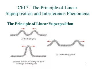
Coil Flux Linear Shaft Motor Principle Shaft u w v u w v u w v S N S N S N S N u w v u w v u w v Thrust Flux Fleming’s law Current
Linear Shaft Motor vs. Linear Motor LINEAR SHAFT MOTOR No influence by change of gap Magnet Coil Core(Iron) Adsorption Force Coil Magnet S N S N S N N S N S N S Cogging by concentration of flux Back York(Iron) Linear motor
Linear Shaft Motor Structure Table Slider(coil) Metal fittings Linear Guide Cable bare Shaft-motor Shaft Linear encoder
Linear Shaft Motor Structure Linear Guide Table Linear Encoder Shaft Holder Plate Shaft Motor Cables
Distinctive FeaturesⅠ Big thrust (6000N) possibility Quiet, no friction during movement Light weight and compact due to no core Simple structure allows building of unit from a short stroke up to 4.6M stroke High resolution (0.14nm), and when combined with high accuracy linear encoder you can achieve high precision positioning
Distinctive FeaturesⅡ It is possible to control speed and positioning with high accuracy by using a linear encoder, even if the mechanical accuracy a little rough. High-speed drive (6.5m/Sec) Low-speed drive (8 μ m/Sec) Almost uniform in speed (±0.006% at 100mm/Sec) Can be used in strong environments such as underwater and in a vacuum When compared to other linear motors, it is compact and lightweight
FV Specified Thrust Output Efficiency F-V Curve • F-V curve shows characteristic of a DC motor (However, the classification for a shaft motor of “The Institute of Electrical Engineers of Japan” is a synchronous motor) • 7000N output (Size of Slider:120 x 120 x 540)
Velocity(V)Current(A) Current(A) Velocity(mm/s) Time Current in Movement • Only at the time of an acceleration and slowdown, current flows. • In case of a linear motor with a core, about 30% of rated current flows even at the time of constant speeding
Data for Temperature Increase CH01:Rm. Tep. CH02:U Coil CH03:V Coil CH04:W Coil CH05:Fin L CH06:Fin R 427Q Temperature Test (6.4A 25%=1.6A) Temperature(C) Process time(1Div=1 h), Total=8h 26m 35s, Highest Tep.=24.5C
Temperature Increase on a Table Load:!kg, V max=1m/s, αmax=1 G Stroke:200mm( Round movement after 1sec stop at at the both ends) Temperature on the table Temperature in the room Temperature increase = Temperature on the table – Temperature in the room Process time Temperature(C)
435Q Thrust(N) Duty Duty Curve • DUTY=Acceleration and slowdown/cycle • In case of a linear motor, constant movement (Duty=1) is not practical. • Technique utilizing duty well is the art of using a shaft motor.
Used with 8.6nm resolution encoder Distance(mm) Time(s) Used with 8.6nm resolution encoder Distance(mm) Repetition Positioning Accuracy • Available within ±1.2 pulses of encoder resolution (3σ)(encoder resolution:less than 10nm) • No influence with Expansion and contraction of a shaft Time(s)
Precise Positioning :Enlargement High Precise Positioning up to ±0.1μm, without overshoot ModelS160T Condition Vmax≒1m/sec αmax≒1G
Performance Characteristics of High Speed Type W Stroke:700mm Speed 3 8 Constant Speed: 3.3m/s Acceleration and slowdown 2 6 1 4 0 2 0 -1 0.10.20.3 0 time(sec) Velocity (m/s) Acceleration |G|
Highest Speed Conditions • 6.3m/sec • Motor:S435Q • Loading:26kg • Stroke:850mm • Encoder:1μm
Lowest Speed 8m/sec Conditions • Velocity:8m/sec • Motor:S320D • Loading:10kg • Stroke:2mm Velocity(mm/sec) Time (sec)
Uniformity in High Speed Uniformity in speed:±0.006% Conditions • Velocity:100mm/sec • Motor:S320D • Loading:10kg • Stroke:220mm • Encoder:0.1m Velocity(mm/sec) Time(sec)
Uniformity in Low Speed Uniformity in speeding:±0.01% Velocity(mm/sec) Conditions • Velocity:5mm/sec • Motor:S320D • Loading:10kg • Stroke:220mm • Encoder:0.1m Time(sec)
Holding Thrust of S435D Thrust(N) Deviation (m) Holding Thrust • Due to servo control, thrust is not held after achieving the position to be programmed • Holding thrust up to the maximum is maintained during operation • Holding thrust depends on the gain • Holding thrust is also depends on the resolution of an encoder
Magnetic Force Distance from surface (mm) Distance from surface:10mm Distance from surface: 5mm Distance from surface: 0mm Magnetic Flux Density(T) Position (mm) Magnetic Field • Magnetic force abruptly decreases when leaving from the surface of the shaft • Very little influence in proportion to the distance from N-S pitch • No relation between the pitch of both poles and positioning accuracy • Thrust field is different from magnetic field
Advantages for Manufacturing Quality Control Saving time in inspection Simple QC in total due to the simple structure Cost Control Low cost in making a guide Basically low cost in structure Process Control High productivity (due to simple assembling) Flexibility of production(Exchangeable in production process) Easy maintenance (In comparison to a conventional liner motor)
Development(Technical Center in Tokyo) • Development and Designing • For Customer Application Production(Iwaki, Odate, Chaina Factories) • Motor, Driver, Controller, Communication System Development and Production Odate Factory(Akita)
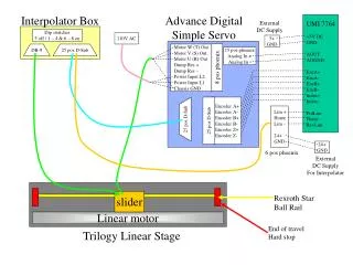
Application of Linear Shaft Motor for Medical Purpose Slider of Shaft Motor Multiple Movement for 4 axes with stepping motor Shaft Motor Limit Sensor with T-NET Limit Sensor with T-NET Controller Unit NPM-104EMBC Movement Sensor with T-NET Slider of Shaft Motor Shaft Motor 3 pcs of Driver for Shaft Motor 2 axes driver for stepping motor NPMC6045-4104 board built-in (4 axes control) NPMCTNET-I/O 104 board G9001 built-in
Business for Linear Shaft Motor Development of Motor : GMC Hillstone Development of Peripherals : Nippon Pulse Motor Production of Motor : GMC Hillstone Nippon Pulse Motor Production of Peripherals : Nippon Pulse Motor Sales of System Actuator : Nippon Pulse Motor
System of Actuator Motor and Driver Motor, Driver and Controller Motor, Driver, Controller and Encoder Motor, Driver, Controller, Encoder and Communication System 5. ? 6. ? Propose with Module Actuator Supply to Our Customers with the Best Module Actuator
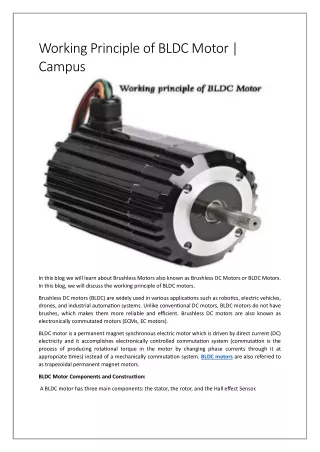
What is a shaft motor? Magnet Coil This is a direct drive-linear-servomotor which is controlling movement by switching on the current to the shaft arrayed inside with magnets and the coil rolled in the shape of a cylinder Linear guide Features of a shaft motor Table Shaft Linear encoder • Quiet, no friction during movement • Big thrust (6000N) • Repetition of position accuracy is available in 0.1μm. • Compared with the other drive system, it is very stable in speeding and possible to control with stable speed. • Possible to operate by a high-speed drive (6.5 m/Sec) to low-speed drive (8μm /Sec). • Can be used in strong environments such as underwater and in a vacuum. • A system is compact and simple. 1 head of a shaft motor is used at the Y-axis 2 heads of a shaft motor are used at the X-axis Slider Magnet shaft Shaft holder Moving part (coil) Cables for encoder Cables for moving part Structure of a shaft motor Application • Using high resolution High precision position accuracy • Using stability in speeding and less than 0.05% of unevenness of movement Precise measurement • Using 0.1μm of repetition positioning accuracy Pinpoint alignment • A system can be compact and it can build simply. System design with high flexibility Summary