Download
1 / 25
250 likes | 297 Views
Learn about the integrated system of SiD's vertex detector and outer tracker for precise measurements and momentum reconstruction. Details on detector opening, servicing, and materials are included in this comprehensive overview.

E N D
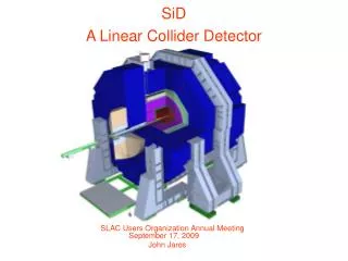
SiD Vertex Detector Mechanics (Layer 1) (Layer 5) Bill Cooper Fermilab VXD
General Considerations • The vertex detector and outer tracker act as an integrated system. • The vertex detector is intended to provide precise vertex determination and initial measurements of momentum. • The outer tracker improves the precision of momentum measurements and reconstructs trajectories into the calorimeters. • The vertex detector can provide measurements of far forward (and backward) trajectories which are beyond the outer tracker acceptance. • Both the vertex detector and the outer tracker reside in the space between the beam pipe and the central electromagnetic calorimeter (EM). • Solenoid, hadronic calorimeter, and muon system costs limit the outer radius of EM, hence the outer radius of the tracker. • Beam-related pair backgrounds set the beam pipe profile, hence the inner radius of the vertex detector. • The transition radius from vertex detector to outer tracker (~200 mm for SiD) depends upon the B-field, the inherent precision of sensors, the number of sensor layers, and multiple scattering contributions. < 5 μm in each coordinate σpT/pT2 < 5x10⁻⁵/GeV CLIC WG4 Meeting – 20 May 2010
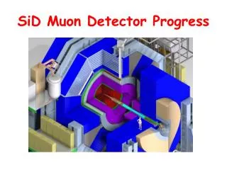
SiD Open for Servicing the VXD • Detector opening distances, the transition radius from VXD to outer tracker, and the dimensions and support of the VXD and beam line elements were chosen with servicing the VXD in mind. CLIC WG4 Meeting – 20 May 2010
General Considerations • For SiD, the vertex detector was designed with top and bottom halves to allow assembly around the beam pipe and servicing. • Servicing requirements led to an agreement that vertex detector support and infrastructure should not extend in radius beyond ~200 mm. • In summary, servicing plus the inner radius of the outer tracker set the maximum radius of vertex detector structures. • Track reconstruction and momentum measurement set the radial extent of the outer tracker. • The vertex detector inner radius is set to avoid beam-related pair backgrounds. CLIC WG4 Meeting – 20 May 2010
Vertex Detector Elevation View • A barrel / disk geometry was assumed for SiD. • Barrel “sensor” length = 125 mm • Disk outer radius (varied with time) = 75.6 mm (central 8 disks) • Dimensions of the 6 disks at larger ׀z׀ were adjusted to match coverage of the outer tracker. • Outer radius of the smallest beam pipe section = 12.4 mm • Outer radius of the support cylinder = 184.7 mm CLIC WG4 Meeting – 20 May 2010
Vertex Detector Barrel End View • Two sensor active widths: 8.6 mm (L1) and 12.5 mm (L2-L5) • Carbon fiber end rings provide support and control out-of-round 108 r-phi locations • Sensors are glued to one another near their long edges to form half-cylinders. • Top and bottom halves allow installation around the beam pipe. • Hermeticity is good. CLIC WG4 Meeting – 20 May 2010
End View of VXD Barrel and Supports Web structure would probably be conical to improve Z-stiffness Double-walled, carbon fiber, outer support cylinder Separation line between upper and lower half-cylinders Longitudinal strips (“ribs”) separate the walls Cooling gas flow passage (60 total) CLIC WG4 Meeting – 20 May 2010
Barrel End View with Cables • Cable contributions to material are significant. • The original goal of 0.1% X0 per layer did not include cables. CLIC WG4 Meeting – 20 May 2010
What about other approaches? • During the last meeting, Joel Goldstein described silicon on foam structures developed at RAL and UK universities. • Both silicon-foam and silicon-foam-silicon ladders were investigated. • Excellent results were obtained for thermal stability with large temperature changes. • An impressive accomplishment for the asymmetric silicon-foam geometry • Obtaining foam with a low enough density has been an issue, though progress on that, and foam machining, has been made. • Sensor flatness after gluing could be an issue. • It may be necessary to measure and characterize the geometry of each “ladder” for this, or any other, approach. • Longer barrels without disks have been considered. CLIC WG4 Meeting – 20 May 2010
What about other approaches? • Yasuhiro Sugimoto has led work in Japan on silicon-foam-silicon ladders. • Their designs meet the goal of 0.1% X0 per silicon layer. • Longer barrels have been considered, but with some disks. CLIC WG4 Meeting – 20 May 2010
Longer Barrels (spring 2008) Simple glue or wedge Retention of ladders • LCFI • Both approaches have interesting features, assume foam as a structural element, and have evolved since this slide was first made. • KEK Main bulkhead (SiC) SiC Ladders Silicon – foam – silicon ladders Strain relief bulkhead CLIC WG4 Meeting – 20 May 2010
Is sensor support realistic? • The honest answer is that we aren’t sure. • The support cylinder concept should be fine. • The issue is whether gluing sensors to one another produces a sufficiently durable structure. • The sensors themselves guide straightness and flatness of the completed structure. • Thermal and gravitational distortions (on paper) should be acceptable. • We have glued 0.075 mm silicon together to form half cylinders. • That worked, but the sensors were fragile and we learned to break them. • The breaks were in the silicon, not in the glue joints, and extended the full silicon length. • We didn’t get to the point of attaching silicon to end rings, which would address out-of-round bending. • In summary, this is a low-mass solution, but we would need to develop better techniques and there might still be problems. CLIC WG4 Meeting – 20 May 2010
Material • Radiation lengths versus angle as presented in the February 2007 tracker review. • At normal incidence, outer tracker = 0.95% X0 per layer. • Vertex detector = 0.22% X0 per layer. • The original goal of 0.1% per layer for the vertex detector did not include cables and services. • Achieving 0.1% is still not easy, but it also isn’t the whole picture. • The cables need to be taken into account. CLIC WG4 Meeting – 20 May 2010
Power Delivery • Cable contributions appear to be dominated by power delivery. • Assumptions for the SiD barrel: • Many assumptions are sensor dependent and could change. • 20 watts average power dissipated at the barrel and a power cycling factor of 80 (1600 watts dissipated at the barrel when ramped up) • Power distributors located 0.3 m from sensors. • Serial powering of ladders occurs at the distributors. • Serial powering within ladders as well. • 0.4 volt drop in cables to ladders and back • 2.9 volts at distributors (2.5 volts at ladders) • Ladder length = 125 mm. • Current per ladder is proportional to the ladder width (8.6 mm for layer 1, 12.5 mm for layers 2-5). • Then when powered “up” • 256 watts dissipated in cables (16% of barrel power) • Current per end when up = 2.11 amp for layer 1 and 3.07 amp for layers 2-5. • Average power density at sensor over a cycle = 142 µW/mm2 CLIC WG4 Meeting – 20 May 2010
Power Conductor Sizing • Assume aluminum conductor with ρ= 2.8 x 10⁻⁶ ohm-cm. • Assume a conductor length of 60 cm and that 16% of sensor power is dissipated over the 30 cm cable length. • Width available = 6.4 mm (Layer 1), 8 mm (Layers 2-5) • Assume width used = 4 mm (Layer 1), 5.6 mm (Layers 2-5). • Then conductor thickness = ~ 23 µm (22.2 µm for Layer 1). CLIC WG4 Meeting – 20 May 2010
Material • SiD all-silicon layout with disks, 0.08 mm thick sensors Barrel-disk overlaps lead to bumps in the material distribution. CLIC WG4 Meeting – 20 May 2010
Material • SiD “ladder” locations, long ladders, no disks, 0.08 mm thick sensors While cabling may seem simpler with a longer barrel, power still needs to be delivered to sensors near Z = 0. CLIC WG4 Meeting – 20 May 2010
Beam Tube Profile • The profile was based upon avoiding the pair backgrounds (backgrounds were calculated by Takashi Maruyama). • The results vary with magnetic field, accelerator, and beam delivery assumptions • These calculations will need to be redone for CLIC. • The goal is maximizing silicon acceptance, which effectively means placing silicon as close to the envelope of beam background as possible. • For simplicity, SiD chose a central straight section with conical sections upstream and downstream. • Two conical sections at different angles could be considered on each side of Z = 0. 500 GeV Nom., 5 T, 14 mrad, no DID R (cm) Z (cm) CLIC WG4 Meeting – 20 May 2010
Beam Tube • The central portion of SiD beam pipe is beryllium, has an inner radius of 12 mm, and a wall thickness of 0.4 mm. • Though care is needed, fabrication of that straight portion based upon boring a solid beryllium billet has been tested in fabrication of Run IIb beam pipes for D0 and CDF. • Fabrication was by Brush-Wellman. • The D0 beam pipe has an inner radius of 14.22, a wall thickness of 0.5 mm, and beryllium sections of length up to 762 mm. • Alternative constructions typically have a longitudinal joint which adds significantly to material, protrudes both inward and outward, and can leak. • For that reason, I recommend fabrication from billet. • Billet costs increase as the square of radius for reasonable lengths. • A portion of conical extensions would also be beryllium. • Methods to join the conical and straight portions via aluminum brazing are known and have been demonstrated for straight sections. • Whether the conical portions should be fabricated from billet is less clear. • Boring beryllium cones has not been demonstrated. • Flexibility remains in the Z at which a transition is made from beryllium to stainless steel . CLIC WG4 Meeting – 20 May 2010
Beam Tube • The beam tube supports and locates the vertex detector. • Because the central, straight section of beam pipe is relatively weak and flexible, stiffening needs to be provided. • Stiffening is provided by the vertex detector outer support cylinder. • Loads are transferred from the beam tube into the support cylinder at four Z-locations. • In a very real sense, the support cylinder becomes a structural component of the beam tube. • Methods to address differential thermal contraction of the support cylinder and the beam tube are essential. CLIC WG4 Meeting – 20 May 2010
Barrel Cooling • Dry air was assumed to enter the barrel at a temperature of -15o C. • (Results with dry nitrogen would be nearly identical) • We assumed no heat transfer from the beam pipe to the innermost layer, that is, the beam pipe would have thermal intercepts. • A total power dissipation of 20 watts was assumed for the barrel. • Based upon the results, that seems reasonable. • For NRe = 1800 and maximal openings in end membranes, average velocity = 1.7 m/s; maximum velocity (between L1 and the beam tube) = 4.6 m/s. • Results as a function of layer are shown on the transparencies which follow. CLIC WG4 Meeting – 20 May 2010
Barrel Cooling CLIC WG4 Meeting – 20 May 2010
Barrel Cooling CLIC WG4 Meeting – 20 May 2010
Comments on Cooling • All of this is fine, but LCFI observed that roughly an order of magnitude more power can be removed. • The low flow rates assumed in the original analysis were intended to ensure that gas flow would not generate vibrations. • Providing laminar flow is a critical part of that. • Turbulent flow will certainly remove more heat per unit area, but then requires vibration studies. • In the end, sensor developments will determine how much effort should go into controlling power dissipation and how much should go into vibration studies. • The paths for delivering cool gas need to be understood better. • The SiD design provided flow distribution via the vertex detector support cylinder. • A clear path should be specified for delivering cool gas to the support cylinder. • Heat exchangers within the overall detector volume (but outside the vertex detector region) are an option which would allow either water-based cooling or evaporative CO2 cooling. • Well insulated lines from the outside world may be a viable option, but they will take space. CLIC WG4 Meeting – 20 May 2010
In Conclusion • The SiD design is a reasonable starting point for CLIC. • The beam tube shape and the inner radius of the vertex detector would need to be adjusted to take into account CLIC backgrounds. • Radii of vertex detector elements may need to be adjusted to provide the required measurement precision. • The transition radius from vertex detector to outer tracker should be evaluated. • The best approach for building barrel layers isn’t clear. • Other methods than the SiD baseline are very promising. • Longer barrels are an option. • Power delivery and cabling are significant issues. • Prototyping of the support cylinder and beam tube should be done and could begin whenever resources are available. • Cooling by flow of dry gas should work, but the flow rate would need to be properly matched to power dissipation once sensors have been selected. • Delivery of cooling gas should be given attention. CLIC WG4 Meeting – 20 May 2010