Download
1 / 30
300 likes | 468 Views
ESS CONVENTIONAL FACILITIES MAIN MILESTONES OF THE PRESENT STUDY PHASE PROGRAMME OF WORK AND ORGANISATION MAIN TECHNICAL OPTIONS MASTER PLAN DRAWING. SCOPE OF THE CONVENTIONAL FACILITIES. Site Reference site for programme, costs and schedule Site characterization

E N D
ESS CONVENTIONAL FACILITIES MAIN MILESTONES OF THE PRESENT STUDY PHASE PROGRAMME OF WORK AND ORGANISATION MAIN TECHNICAL OPTIONS MASTER PLAN DRAWING PAUL GIOVANNONI date : 24/10/2014
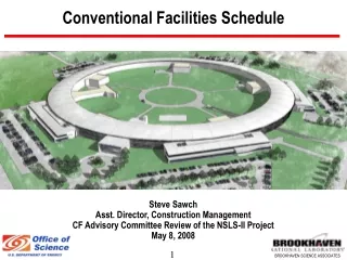
SCOPE OF THE CONVENTIONAL FACILITIES Site Reference site for programme, costs and schedule Site characterization Site preparation for construction (earthwork, roads, …) Buildings Front End / Linac tunnel / Klystron buildings Ring buildings Targets and instruments buildings Beam stop buildings Central helium and RF test buildings Central laboratory and office building Infrastructures Water systems and associated networks (potable water, cooling, … ) HVAC Electricity Computer network PAUL GIOVANNONI date : 24/10/2014
CONVENTIONAL FACILITIES IMPACT ON THE ESS PROJECT Conventional facilitiescan easily represent about 30% of the total project budget and are inevitably on the critical path of the project time schedule To control conventional facilities costs and project schedule we have to : -identify main possible technical options for each conventional facilities subsystem - associate to each of them a cost estimate as precise as possible - adopt the most economical (combining investment and operation) technical options - analyse the impact on the planning of construction We use : SNS, CONCERT and Vol III of ESS programmes PAUL GIOVANNONI date : 24/10/2014
THE MAIN MILESTONES OF THE PRESENT PHASE OF STUDY May 2002 : Final proposal and presentation in Bonn January 2002 : Document on : · technical options with the evaluation of the TAC, · timescale for the Conventional Facilities, from the design to the start of operation, with the evaluation of the TAC, · cost estimates submitted to Council for approval. January 2002 : Presentation to the TAC of main technical options PAUL GIOVANNONI date : 24/10/2014
DP2I : Drawings and calculation reports Cost evaluation PROGRAMME OF WORK AND ORGANISATION SNS AND CONCERT EXTRAPOLATIONS ELABORATION OF TECHNICAL OPTIONS SNS Interface design parameters Schemas RF calculations by SACLAY for ESS 10 MW Files ESS UTILITIES LOAD SUMMURY PAUL GIOVANNONI date : 24/10/2014
EXAMPLES OF DOCUMENTS 1) ESS LOAD SUMMURY 2) FILES 4) WBS 3) SHEDULE PAUL GIOVANNONI date : 24/10/2014
Earth material 220 m 220 m 152 m 152 m 114 m 114 m 7 m 8 m Ground level 6 m 6 m 3 m 3 m Linac tunnel F.E. F.E. SDTL SDTL CCL CCL SC SC ß ß =0.68 =0.68 SC SC ß ß =0.86 =0.86 56 m 56 m 58 m 58 m 75 m 75 m 92 m 92 m 205 m 205 m 20 20 MeV MeV 85 85 MeV MeV 185 185 MeV MeV 450 450 MeV MeV 1 334 1 334 MeV MeV 486 m 486 m LINAC TUNNEL : TECHNICAL OPTIONS CONCERT option : Linac tunnel is just buried and covered by earth material (3 m at the beginning to 7 m at the end) SNS option : same thickness of earth material all along the linac tunnel Advantages : Limitation of earth material quantity Drawbacks : Variation of compression along the linac but we assume that quasi linear settlement is not a problem PAUL GIOVANNONI date : 24/10/2014
Klystron building Retaining wall 1.5 m Wave guide Linac tunnel Chase LINAC TUNNEL TECHNICAL OPTIONS (cont’d) SNS type option : Klystron building very close to linac tunnel Advantages : - wave guides length is limited - schedule : possibility to build linac tunnel and klystron building independently and in parallel Klystron building Retaining wall 1.5 m Wave guide 7 m 8 m 5 m 5 m Linac Drawbacks : - retaining wall results in increase of cost in comparison with CONCERT option tunnel Chase PAUL GIOVANNONI date : 24/10/2014
LINAC TUNNEL : TECHNICAL OPTIONS (cont’d) CONCERT option : light metallic structure for the klystron building Klystron building Earth material Metallic siding 8 m 7 m 11 m 9 m Wave guide Linac tunnel 3.5 m 5 m Advantages : - limitation of the klystron building cost - schedule : possibility to build linac tunnel and klystron building independently and in parallel Drawbacks :Length of the wave guides is very long PAUL GIOVANNONI date : 24/10/2014
SIZE OF THE RETAINING WALL FOR RADIOLOGICAL PROTECTION Retaining wall 1 W/m and 0.5 microSv/h 1,5 M 0,6 m 5m Linac Tunnel PAUL GIOVANNONI date : 24/10/2014
LINAC TUNNEL TECHNICAL OPTIONS (cont’d) LOS ALAMOS type option : linac tunnel buried deeply, ~ -8 m, and klystron building on top Advantages : - easy to connect and disconnect klystrons and pipes from klystron building to linac - need less surface than in other options because no earth material - constant earth compression of the tunnel Drawbacks : - water table must be deeper than in other options - HEBT, ring, RTBT and may be Front End building, buried deeply at the same level than the linac, so may be more expensive than in other options - schedule : impossible to build linactunnel and klystron building in parallel PAUL GIOVANNONI date : 24/10/2014
LINAC TUNNEL TECHNICAL OPTIONS (cont’d) « No buried construction » option : linac tunnel on the floor and at the same ground level as klystron building Advantages : - water table less problematic - no trench Drawbacks : -more earth covering to shield linac tunnel but also HEBT, ring, RTBT -uneasy connection of wave guides and pipes from klystron to linac building Considered as unattractive PAUL GIOVANNONI date : 24/10/2014
LINAC TUNNEL TECHNICAL OPTIONS (cont’d) Conclusion on the linac tunnel option LOS ALAMOS and « NOT BURIED LINAC »options are not retained CONCERT AND SNS OPTIONS : Lower cost for klystron building in case of CONCERT option but length of wave guides longer than in SNS option so we need to study in more details these two options in order to have a better estimate of the cost difference Construction and cost will depend on the characteristics of the underground. Extra costs resulting from deviations from the reference site to be added to the site premium (additional contribution from the host country) PAUL GIOVANNONI date : 24/10/2014
LINAC TUNNEL TECHNICAL OPTIONS (cont’d) Chases connecting linac tunnel to klystron building We propose the same chase concept as that of SNS Klystron building Klystron building In these chases we find the following equipment : wave guides, chilled water pipes electrical cables Retaining wall Retaining wall 1.5 m Wave Wave guide guide 8 m 8 m 5 m 5 m Linac Linac tunnel tunnel Chase Chase These parts are fixed on a special support This support is put into the chase Inside a chase, wave guides are cooled down by chilled water pipes PAUL GIOVANNONI date : 24/10/2014
Klystron wall Earth material Coupler Tunnel Cryomodule Q pole … KLYSTRON BUILDING : TECHNICAL OPTIONS Goal : minimize costs and therefore area Two constraints : 1)The short distance between couplers in the SC part (average : 2 m) - difficulty to put Klystrons side by side - high chaze density 2) The large size of the power supplies : 10 m x 8 m PAUL GIOVANNONI date : 24/10/2014
PAUL GIOVANNONI date : 24/10/2014
KLYSTRON BUILDING TECHNICAL OPTIONS (cont’d) option : - all equipment are in the klystron building ( RF, power supplies, cooling equipment, HVAC, electronics racks, diagnostics, vacuum control, quadrupole power supplies, etc ) • klystrons are in a vertical position, side by side -some mechanical equipment like HVAC, DI water system and rf power supplies are in alcoves. This results in a reduction of the building surface -metallic structure with double skin siding -utilization of air pads and fork lifts to move klystrons and other loads instead of travelling crane (to reduce the building height) PAUL GIOVANNONI date : 24/10/2014
POSITIONNING OF KLYSTRON BUILDING and CHL/RF BUILDING Klystron building : Length = 430 m / Height = 6 m Beam axis 30 m 30 m 40 m 35 m 35 m Alcoves 18,5 m 25,5 m Front End building 37 m 62 m >190 m CHL/RF building PAUL GIOVANNONI date : 24/10/2014
personnel access HEBT Linac tunnel truck access 30 m 30 m 40 m 35 m 35 m Alcoves 30 m Front End building Klystron building truck access ACCESS ALONG THE LINAC TUNNEL (cont’d) 1 truck access at the beginning of linac tunnel by the front end building 1 truck access in the HEBT tunnel 6 personnel access 80 m between each access PAUL GIOVANNONI date : 24/10/2014
8 m 4 m 4 m Access building on the ground floor (metallic structure) 4 m 2 m 2 m 8 m 5 m LINAC TUNNEL 2 m PERSONNEL ACCESS PAUL GIOVANNONI date : 24/10/2014
10 MW Low energy linac power distribution 20kV 185 MeV 1 2 3 1 diacrodes 1 diacrodes 1klys 1klys 3klys 3klys RFQ1 H-2 RFQ1 H-1 RFQ2 H-2 RFQ2 H-1 DTL1 H-2 DTL1 H-1 4 5 6 HVPS 4MVA 2klys 3klys 10klys 10klys 10klys SDTL RFQ3 H+ DTL2 H+ CCL CCL PAUL GIOVANNONI date : 24/10/2014
10 MW High energy linac power distribution 185 MeV 450 MeV 1 2 3 16 klystrons 15 klystrons 14 klystrons 1 16 17 32 31 45 450 MeV 1334 MeV 5 6 7 8 13 11 klystrons 10 klystrons 10 klystrons 9 klystrons 9 klystrons 57 67 68 77 78 87 88 96 133 141 = 0.68 20 kV HVPS 4MVA = 0.86 4 11 klystrons 46 56 PAUL GIOVANNONI date : 24/10/2014
HVAC • Utilization of Air blast radiators to cool raw water • - Choice of the water pressure and the cooling temperatures values and their variations for process equipment • Local hvac or little plant for offices, laboratories, and test areas • Air conditioning units distributed along tunnels to keep right temperature when the beam is on • HVAC from FE an other parts to remove air in the tunnels before coming into (70 mn) PAUL GIOVANNONI date : 24/10/2014
HVAC (cont’d) Temperature in the tunnels with beam : To Be Determined Temperature in the tunnels without beam after 70mn of ventilation : To Be Determined Temperatures in the FE : To Be Determined Temperatures in Klystron building : To Be Determined Temperature in the ring …. and other buildings : To Be Determined PAUL GIOVANNONI date : 24/10/2014
BEAM DUMPS Linac beam dump : Passive or actif , depend on the power on the beam dump ? Injection beam dump : power on the beam dump ? Extraction beam dump : Passive or actif , depend on the power on the beam dump ? PAUL GIOVANNONI date : 24/10/2014
RING The same than ESS PAUL GIOVANNONI date : 24/10/2014
TARGET SHORT PULSE The same than SNS extrapolated to 5 MW PAUL GIOVANNONI date : 24/10/2014
TARGET LONG PULSE The same than SHORT PULSE PAUL GIOVANNONI date : 24/10/2014
MASTER PLAN Target Short Pulse Guest House Central Laboratories and offices Access Achromat 750 m Target Long Pulse CHL/RF Klystron building Central Utility Building 1300 m PAUL GIOVANNONI date : 24/10/2014
MASTER PLAN Building implantation : CLO close Target buildings Advantages : easy access for users Guest house : one module of 60 rooms at the beginning of the operations, an other 60 rooms the third year and an other the seventh year Avantages : construction cost reduction COMPONENT ASSEMBLY Technical option : RFQ , DTL, SDTL, CCL and SL will be assemble in the shop company, outside the site. These components will be installed and tested inside the Front End and Linac Tunnel. Justification : To avoid buildings on the site for assembling components (cost reduction) and time reduction for the schedule. PAUL GIOVANNONI date : 24/10/2014