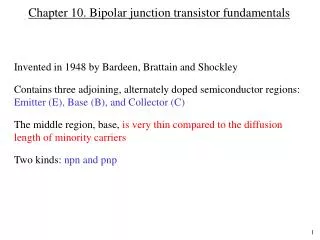
The Bipolar Junction Transistor ( B.J.T.)
480 likes | 926 Views
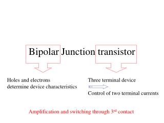
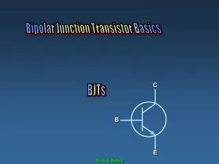
The Bipolar Junction Transistor ( B.J.T.). Symbols. How to remember the Symbols. The NPN transistor has an arrow that is: N not P pointing N in. Transistor Biasing. The base emitter junction must be forward biased. The base collector must be reverse biased.

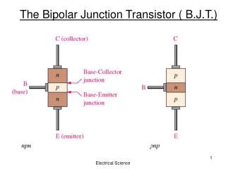
The Bipolar Junction Transistor ( B.J.T.)
E N D
Presentation Transcript
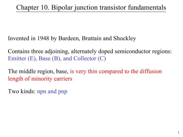
The Bipolar Junction Transistor ( B.J.T.) Electrical Science
Symbols Electrical Science
How to remember the Symbols • The NPN transistor has an arrow that is: • N not • P pointing • N in Electrical Science
Transistor Biasing • The base emitter junction must be forward biased. • The base collector must be reverse biased. Add the two batteries to the circuit on the right.Use the correct bias. What type of transistor is this ? Add Electrical Science
Transistor Currents This Rule must be memorised! Electrical Science
Question A transistor has a collector current of 0.1 Amps. The base current is 100 micro Amps. Find the emitter current, in milli amps. Electrical Science
Solution: First we convert all units to milli amps: • Collector current = 0.1 Amps. This is 100 milli Amps. Base current is 100 micro Amps. This is 0.1 milli amps. 2) The formula: Emitter current = 0 .1 mA + 100 mA. Emitter current = 100 .1 mA Electrical Science
How transistors work A small tap can control the flow of water from a pressure hose. Tap = Base A small signal on the base of a transistor can control the flow of current from collector to emitter. Electrical Science
A Transistor amplifies signals. Unlike a resistor or capacitor. a transistor must be powered By a battery. We say it is an active device. V out V in The transistor makes the signal louder. A small signal is sent in. A large signal comes out. For example a radio receives a weak signal at the aerial Vin. It is amplified using a transistor and sent out to the speaker V out. The battery power supply is called Vcc, because the voltage is connected indirectly to the collector. Electrical Science
Using an analogue meter to test Transistors Electrical Science
12 V V + o Vce Vc V 5 V Vbe V V Testing a Transistor in Circuit with a multimeter Vcc Vbb The Base Emitter PN junction uses 0.7 volts to turn on the transistor, which joins the collector to the emitter. Question: a)State the voltage reading on each meter. b) Name these voltage readings. Vcc,Vce,Vbe, Vbb. Electrical Science
Parameters • Current Gain: 2) CURRENT Transistor can only carry a limited current. If the maximum current is exceeded the transistor will overheat and be damaged. 3) POWER: Transistor can only dissipate a limited amount of power. If the maximum power is exceeded the transistor will overheat and be damaged. Electrical Science
Question A transistor has a maximum power rating of half a watt. It’s maximum voltage supply VCE is 20V and maximum current IC is 50 mA. • Fill in the following grid. • Will any of these situations damage the transistor? Electrical Science
Solution a) b) Yes. When the current is100mA the limit is exceeded, and the transistor damaged. Electrical Science
Heat Sinks • To cool down some transistors metal plates are attached to them. • Without these heat sinks they would overheat. • These remove heat from the transistor just like the metal fins on a motor bike, or a radiator in a car. Electrical Science
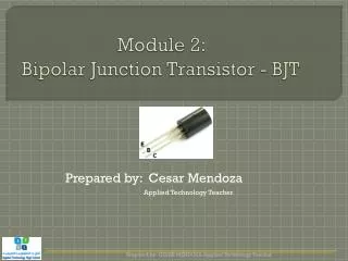
Transistor Cases base collector emitter Electrical Science
The Transistor as a Switch.The LED will light because the Base has more than 0.7V which turns the transistor on so the collector is connected to the emitter.Find the voltage at A. Resistor A 500 Electrical Science
1K A Resistor 50 The Transistor as a Switch.This LED will NOT light because the Base has less than 0.7V which turns off the transistor and so the collector is disconnected from the emitter. Find the voltage at point A. Electrical Science
Is the LED on ? Explain your answer 1k Solution: The LED is off because the transistor is on and so short circuiting it. On means collector is connected to emitter. 9k Electrical Science
State the voltage bias on the base. A Resistor Solution : The voltage at the base is 9.38 Volts. Electrical Science
Question • If the current gain BDC is 50 find • IB • IC • IE • VB • VC Electrical Science
VC Ic IB IE VB Electrical Science
Solution a) • First we find IB • IB is the current in the base. • Current is V/R • V is 3 - 0.7 dropped by the base emitter PN junction. • The base current = 2.3/10,000 • IB = 0.000230 Amps. • IB = 0.230 milli Amps. • IB = 230 micro Amps. Electrical Science
Solution b) • To find IC • We know: Gain means output compared to input. • Gain = IC / IB • Multiply both sides by IB • Gain IB = IC IC = 50 . 230 u Amps IC = 11500 u Amps • IC = 11. 5 mA. Electrical Science
Solution c) • To find IE. • IE = IC + IB • =11.7 mA • Solution d) • VB is always 0.7 volts higher than the voltage at the emitter. • In this case the emitter is grounded so VB is 0.7 volts • Solution e) • Vc is Vcc – the voltage dropped across Rc. • Vc = 20 – (11.5 mA)(1 k) • Vc = 8.5 volts. Electrical Science
R5 = 120 ohms Question: The transistor is not fully on. We say it is not saturated. • You measure the voltage across R1 as 4.5 volts. • Find Vce. • b) R5 uses 0.1 m Volts. • Find the current through it. • c) Find Ic. • d) Find the current Gain of the circuit. • e) Find Ie. Electrical Science
Answer • A) The supply is 10 volts • R1 uses 4.5 volts. • R2 uses 4.5 volts. Same resistance and current. • The diode used 0.7 volts. • These add up to 9.7 volts. • So the transistor uses 0.3 volts between collector and emitter and this is called Vce. • B) Using Ohms Law : Electrical Science
c) Solution( Use Ohm’s Law) Electrical Science
Solution part d Electrical Science
Q15 March 2005 Redraw the transistors and show the direction of conventional current Electrical Science
Q15 March 2005 - + N P + - P N N P - + • Solution: • Fill in the P and N terminals. • Fill in the battery + and -. • The Base emitter must be forward biased. The base collector reverse biased. Electrical Science
Q15 March 2005 - + N P + - N P N P - + Solution: Conventional current flows from the + of the battery to the – of the battery. Electrical Science
Q15 May 2005 The hfe of an NPN transistor is 250. If the transistor is operating under non-saturated conditions in a circuit and the collector current found to be 25mA determine the base current. Electrical Science
Solution 100 micro amps. Saturation: means the transistor is turned on fully. Increasing the voltage on the base will have no effect. Electrical Science
Question A transistor circuit has the follow measurements. Vcc 30 V IB = 0.25 mA Ic = 50 mA Find IE. Electrical Science