Download
1 / 16
160 likes | 333 Views
The Wave Equation Modeled We’ve looked at what happens to P-waves in the simple two-layer case. The Wave Equation Modeled …we get a direct P- wave, a refracted P- wave, and a reflected P- wave. The Wave Equation Modeled So, you can now easily find the three P-wave phases:.

E N D
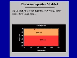
The Wave Equation Modeled We’ve looked at what happens to P-waves in the simple two-layer case...
The Wave Equation Modeled …we get a direct P-wave, a refracted P-wave, and a reflected P-wave.
The Wave Equation Modeled So, you can now easily find the three P-wave phases:
The Wave Equation Modeled …but, as you saw in your lab field data, real data adds the complication of other phases–here, the air wave and ground roll (Rayleigh wave) are shown.
Multilayer Model Remember, for refraction data you generally only need to know the first arrivals… Distance Direct Wave 1st Layer Refraction Time 2nd Refraction
Reflection/Refraction • Refraction Advantages: • Small number of sources/receivers can work • Little signal processing is needed • Interpretation straight forward • Reflection Advantages: • Small scale features can be resolved • No restriction on velocity-depth profile • Can be used in regions of complex geology • Uses entire reflected wavefield • Subsurface directly imaged
Seismic Reflection Terms: Stacked Section/Seismic Section:A plot of seismic reflection data with substantial digital processing that represents a zero-offset profile. Time Section:A seismic section in which the axes are offset and two-way travel time. Rarely represent correct spatial positioning of subsurface features. Depth Section:A seismic section in which the time section has been converted to depth through a velocity model.
Seismic Reflection Data Processing Steps Unlike refraction data, there are many processing steps to create an image of the subsurface with seismic reflection data. Many of these are not trivial, and we will look at some of them in lab. Poorly processed seismic data can be made to look like just about anything. You’ve been warned!
Seismic Reflection Data The basis of common midpoint (CMP) processing is to create a stacked profile representing a zero-offset section. CMP processing is the current industry standard.
Seismic Reflection Data Processing Problems… Best Data Poorly Processed Data
Seismic Reflection Data Examining Raw Data...
Seismic Reflection Data Examining Raw Data… Be aware that seismic datais as varied as geologic settings, and thus can look very different.
Seismic Reflection Data Digital filtering is a critical processing step...
Seismic Reflection Data You data can be analyzed in other domains as well as the frequency domain.