Projections
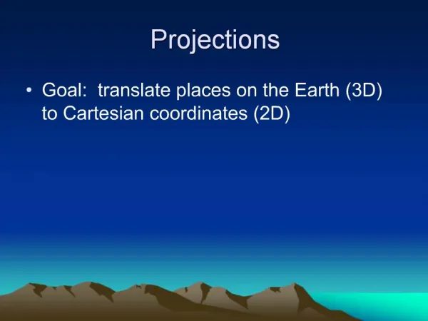
Projections. Projection. Demo. Projections - Outline. 3D Viewing Coordinate System & Transform Process Generalized Projections Taxonomy of Projections Perspective Projections Parallel Projections. 3D Viewing. Inherently more complex than 2D case. Extra dimension to deal with

Projections
E N D
Presentation Transcript
Projections Projection Graphics
Demo Graphics
Projections - Outline • 3D Viewing • Coordinate System & Transform Process • Generalized Projections • Taxonomy of Projections • Perspective Projections • Parallel Projections Graphics
3D Viewing • Inherently more complex than 2D case. • Extra dimension to deal with • Most display devices are only 2D • Need to use a projectionto transform 3D object or scene to 2D display device. • Need to clip against a 3D view volume. • Six planes. • View volume probably truncated pyramid Graphics
Coordinate Systems & Transform Process Object coordinate systems. Transform World coordinates. Clip View Volume Project Screen coordinates. Rasterize Raster Graphics
Body System yv xv P0 zv Front-Wheel System Viewing plane Viewing Coordinate System zw world yw xw Viewer System View Plane View Window Graphics
Specifying the Viewing Coordinate System • Viewing Coordinates system, [xv, yv, zv], describes 3D objects with respect to a viewer. • A viewing plane (projection plane) is set up perpendicular to zv and aligned with (xv,yv). • In order to set a viewing plane we have to specify: Graphics
yv xv P zv Viewing plane zw v L N • P=(Px,Py,Pz) is a point where a camera is located. • L - is a point to look-at. • V - is the view up vector, whose projection onto the view-plane is directed up. yw xw Graphics
Viewing Window • After objects were projected onto the viewing plane, an image is taken from a Viewing Window. • A viewing window can be placed anywhere on the view plane. • In general the view window is aligned with the viewing coordinates and is defined by its extreme points: (l,b) and (r,t) View plane yv (r,t) xv View window zv Graphics (l,b)
Viewing Volume • Given the specification of the viewing window, we can set up a Viewing Volume. • Only objects inside the viewing volume will appear in the display, the rest are clipped. Graphics
In order to limit the infinite viewing volume we define two additional planes: Near Plane and Far Plane. • Only objects in the bounded viewing volume will appear. • The near and far planes are parallel to the viewing plane and specified by znear and zfar. • A limited viewing volume is defined: • For orthographic: a rectangular parallelpiped. • For oblique: an oblique parallelpiped. • For perspective: a frustum. Far Plane zv Near Plane zv window Far Plane window Near Plane Graphics
window • The Viewing Plane can be placed anywhere along the Zv axis, as long it does not contain the center of projection. Far Plane Near Plane zv Graphics
top right yv xv zv bottom near left far Defining the viewing Volume top right yv xv zv bottom near left far Graphics
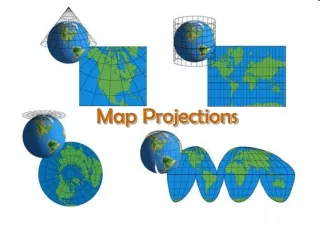
Generalised Projections. • Transforms points in a coordinate system of dimension n into points in one of less than n (ie 3D to 2D) • The projection is defined by straight lines called projectors. • Projectors emanate from a centre of projection, pass through every point in the object and intersect a projection surface to form the 2D projection. Graphics
Projections. • In graphics we are generally only interested in planar projections – where the projection surface is a plane. • Most cameras employ a planar film plane. We will only deal with geometric projections – the projectors are straight lines. • Whether rays coming form object converges to COP or not Graphics
Projections. • Henceforth refer to planar geometric projections as just: projections. • Two classes of projections : • Perspective. • Parallel. Parallel A Parallel A A A Centre of Projection. B B B Centre of Projection at infinity B Perspective Graphics
Projections • Viewing 3D objects on a 2D display requires a mapping from 3D to 2D. • Projectors are lines from the center of projection through each point in the object. • A projection is formed by the intersection of the projectors with a viewing plane. Center of Projection Projectors Graphics
Center of projection at infinity results with a parallel projection.( projection lines are parallel) • A center of projection at a finite distance results with a perspective projection. (projection lines converges to COP) Graphics
A parallel projection preserves relative proportions of objects, but does not give realistic appearance (commonly used in engineering drawing). • A perspective projection produces realistic appearance, but does not preserve relative proportions. Graphics
Planar geometric projections. Parallel Perspective Orthographic Oblique 1 point Axonometric Cabinet Cavalier 2 point Isometric 3 point Multi View A Taxonomy of Projections Graphics
Parallel Projection Projection lines (projectors) are parallel not converges Converges at infinity, COP is infinity Preserve the shape not used for realistic images Parallel line intersect perpendicularly to projection plane-Orthographic Projection When parallel line intersect plane at some angle not perpendicular –Oblique Graphics
When parallel line perpendicularly intersect and View plane is parallel to principal plane (perpendicular to axies ) of object space-Multi view projection (shows one face of object-top, bottom, left, right, front, rear) it includes 2 dimensions(Lxb, bxh, hXL) • When parallel line perpendicularly intersect and View plane is not parallel to principal Plane( not perpendicular to principal axies) of object space-Axonometric projection (isometric, diametric, trimetric) it includes 3 dimensions(Lxbxh) projectors makes equal angel with all three principal axies –isometric • Multi view and orthographic combination provide 3 faces can be seen TFRi, BLRe Graphics
In oblique projection only the face of object is parallel to view plane are shown, their shape, size, length, angle are preserved for these faces only, phases not parallel discarded. In oblique projection Line which is perpendicular to plane is shorter in length of actual line(projection rays )change in length of projected line is –foreshortening factor f • When f=0 projection is orthographic (cot 90=0) angle between projector and plane is 90 • When f=1 then oblique projection is Cavalier projection(cot45=1) angle between projector and plane is 45 • When f=1/2 then oblique projection is cabinet projection or break front or cupboard (cot63.435=1/2) angle is 63.435 Graphics
Parallel Projections • Specified by a direction to the centre of projection, rather than a point. • Centre of projection at infinity. • Orthographic • The normal to the projection plane is the same as the direction to the centre of projection. • Oblique • Directions are different. A Parallel A B Centre of Projection at infinity B Graphics
Parallel Projection • Projectors are all parallel. • Orthographic: Projectors are perpendicular to the projection plane. • Oblique: Projectors are not necessarily perpendicular to the projection plane. Orthographic Oblique Graphics
Orthographic Projection • Since the viewing plane is aligned with (xv,yv), orthographic projection is performed by: (x,y,z) (x,y) yv xv P0 zv Graphics
Lengths and angles of faces parallel to the viewing planes are preserved (Plan View). • Problem: 3D nature of projected objects is difficult to deduce. Top View Side View Front view Graphics
Orthographic: Projector is perpendicular to view plane • Oblique: projector is not perpendicular to view plane • Multi view: View plan parallel to principal planes • Axonometric : View plane not parallel to principal planes Graphics
Orthographic Projections Most common orthographic Projection : Front-elevation, Side-elevation, Plan-elevation. Angle of projection parallel to principal axis; projection plane is perpendicular to axis. Commonly used in technical drawings Graphics
Orthographic Projection Orthographic Projection onto a plane at z = 0. xp = x , yp = y , z = 0. Graphics
Axonometric Orthographic Projections • Projection plane not parallel to principal Plane (not perpendicular to principal axis) normal of plane makes various angle axies • Show several faces of the object at once • Foreshortening is uniform rather than being related to distance(shortening factor f ) • Parallelism of lines is preserved • Distances can be measured along each principal axis ( with scale factors ) Graphics
Isometric Projection • Most common axonometric projection • Projection plane normal makes equal angles with each axis. • i.e normal is (dx,dy,dz), |dx| = |dy|=|dz| Graphics
y y 120º 120º 120º x z x • All 3 axes equally foreshortened • measurements can be made • Hence the name iso-metric Projection Plane z Isometric Projection Normal Graphics
Oblique projections. • Projection plane normal differs from the direction of projection. • Usually the projection plane is parallel to a principal axis. • Other faces can measure distance, but not angles. • Parallel rays intersect view plane at angle β Graphics
cavalier projection : • Preserves lengths of lines perpendicular to the viewing plane. • 3D nature can be captured but shape seems distorted. • Can display a combination of front, side, and top views. Cabinet projection: • lines perpendicular to the viewing plane project at 1/2 of their length. • A more realistic view than the cavalier projection. • Can display a combination of front, side, and top views. Graphics
Oblique projection Normal Parallel to x axis y x Projection Plane z Graphics
y L.sin P´ L z P=(0,0,1) x L.cos Geometry of Oblique Projections • Projection plane is x,y plane • L=1/tan() • - angle between plane and projection direction - Determines the type of projection • is choice of horizontal angle. • Given a desired L and , • Direction of projection is • (L.cos, L.sin,-1) Graphics
Geometry of Oblique Projections • Point P=(0,0,1) maps to: P’=(l.cosa, l.sina, 0) on xy plane, and P(x,y,z) onto P’(xp,yp,0) and Graphics
Oblique Projection • Projectors are not perpendicular to the viewing plane. • Angles and lengths are preserved for faces parallel to the plane of projection. • preserves 3D nature of an object. yv (xp,yp) xv (x,y,z) (x,y) Graphics
Several Oblique Projections 1 1 1 1 1 1 =30o =45o cavalier Projections (=45o) of a cube for two values of angle 0.5 0.5 1 1 1 1 =45o =30o Cabinet Projections (= 63.4o) of a cube for two values of angle Graphics
Perspective Projections. • Defined by projection plane and centre of projection. • Visual effect is termed perspective foreshortening. • The size of the projection of an object varies inversely with distance from the centre of projection. • Similar to a camera - Looks realistic ! • Not useful for metric information • Angles only preserved on faces parallel to the projection plane. • Distances not preserved Graphics
Perspective Projections • A set of lines not parallel to the projection plane converge at a vanishing point. • point at infinity. • Homogeneous coordinate is 0 (x,y,0) Graphics
Perspective Projections • Lines parallel to a principal axis converge at an axis vanishing point. • Categorized according to the number of such points • Corresponds to the number of axes cut by the projection plane. y y x x z z Projection plane Graphics
Painless Perspective Graphics
The eye as a camera Graphics
The eye as a camera Graphics
Equal distances appear smaller Graphics
Simplified camera Graphics
Simplified camera View plane Z-axis Graphics