Download
1 / 1
10 likes | 182 Views
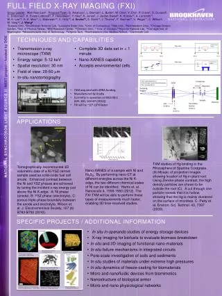
Figure 1: The four XIS sensors. X-ray Imaging Spectrometers (XIS) of Astro-E2. Hironori Matsumoto (Kyoto University) and the XIS team. 3. Back-side illuminated (BI) CCD. 1. Overview.

E N D
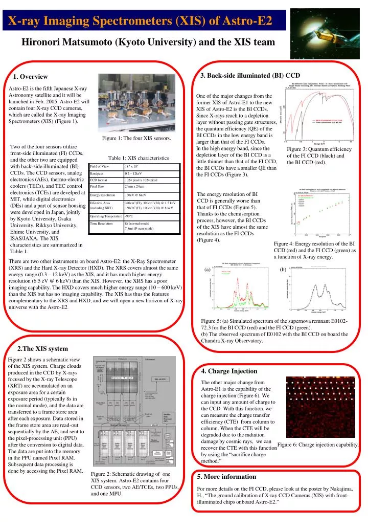
Figure 1: The four XIS sensors. X-ray Imaging Spectrometers (XIS) of Astro-E2 Hironori Matsumoto (Kyoto University) and the XIS team 3. Back-side illuminated (BI) CCD 1. Overview Astro-E2 is the fifth Japanese X-ray Astronomy satellite and it will be launched in Feb. 2005. Astro-E2 will contain four X-ray CCD cameras, which are called the X-ray Imaging Spectrometers (XIS) (Figure 1). One of the majorchanges from the former XIS of Astro-E1 to the new XIS of Astro-E2 is the BI CCDs. Since X-rays reach to a depletion layer without passing gate structures, the quantum efficiency (QE) of the BI CCDs in the low energy band is larger than that of the FI CCDs. In the high energy band, since the depletion layer of the BI CCD is a little thinner than that of the FI CCD, the BI CCDs have a smaller QE than the FI CCDs (Figure 3). Two of the four sensors utilize front-side illuminated (FI) CCDs, and the other two are equipped with back-side illuminated (BI) CCDs. The CCD sensors, analog electronics (AEs), thermo-electric coolers (TECs), and TEC control electronics (TCEs) are develped at MIT, while digital electronics (DEs) and a part of sensor housing were developed in Japan, jointly by Kyoto University, Osaka University, Rikkyo University, Ehime University, and ISAS/JAXA. The XIS characteristics are summarized in Table 1. Figure 3: Quantum efficiency of the FI CCD (black) and the BI CCD (red). Table 1: XIS characteristics The energy resolution of BI CCD is generally worse than that of FI CCDs (Figure 5). Thanks to the chemisorption process, however, the BI CCDs of the XIS have almost the same resolution as the FI CCDs (Figure 4). Figure 4: Energy resolution of the BI CCD (red) and the FI CCD (green) as a function of X-ray energy. There are two other instruments on board Astro-E2: the X-Ray Spectrometer (XRS) and the Hard X-ray Detector (HXD). The XRS covers almost the same energy range (0.3 – 12 keV) as the XIS, and it has much higher energy resolution (6.5 eV @ 6 keV) than the XIS. However, the XRS has a poor imaging capability. The HXD covers much higher energy range (10 – 600 keV) than the XIS but has no imaging capability. The XIS has thus the features complementary to the XRS and HXD, and we will open a new horizon of X-ray universe with the Astro-E2 (a) (b) Figure 5: (a) Simulated spectrum of the supernova remnant E0102-72.3 for the BI CCD (red) and the FI CCD (green). (b) The observed spectrum of E0102 with the BI CCD on board the Chandra X-ray Observatory. 2.The XIS system Figure 2 shows a schematic view of the XIS system. Charge clouds produced in the CCD by X-rays focused by the X-ray Telescope (XRT) are accumulated on an exposure area for a certain exposure period (typically 8s in the normal mode), and the data are transferred to a frame store area after each exposure. Data stored in the frame store area are read-out sequentially by the AE, and sent to the pixel-processing unit (PPU) after the conversion to digital data. The data are put into the memory in the PPU named Pixel RAM. Subsequent data processing is done by accessing the Pixel RAM. 4. Charge Injection The other major change from Astro-E1 is the capability of the charge injection (Figure 6). We can input any amount of charge to the CCD. With this function, we can measure the charge transfer efficiency (CTE) from column to column. When the CTE will be degraded due to the radiation damage by cosmic rays, we can recover the CTE with this function by using the “sacrifice charge method.” Figure 6: Charge injection capability. Figure 2: Schematic drawing of one XIS system. Astro-E2 contains four CCD sensors, two AE/TCEs, two PPUs, and one MPU. 5. More information For more details on the FI CCD, please look at the poster by Nakajima, H., “The ground calibration of X-ray CCD Cameras (XIS) with front-illuminated chips onboard Astro-E2.”