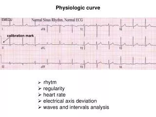
Initial system curve
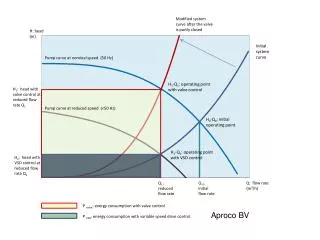
Modified system curve after the valve is partly closed . H: head (m). Initial system curve. Pump curve at nominal speed (50 Hz). H 1 -Q 1 : operating point with valve control. H 1 : head with valve control at reduced flow rate Q 1. Pump curve at reduced speed (<50 Hz).

Initial system curve
E N D
Presentation Transcript
Modified system curve after the valve is partly closed H: head (m) Initial system curve Pump curve at nominal speed (50 Hz) H1-Q1: operating point with valve control H1: head with valve control at reduced flow rate Q1 Pump curve at reduced speed (<50 Hz) H0-Q0: initial operating point H2-Q1: operating point with VSD control H2: head with VSD control at reduced flow rate Q1 Q1: reduced flow rate Q 0: initial flow rate Q: flow rate (m3/h) P valve: energy consumption with valve control Aproco BV P VSD: energy consumption with variable speed drive control
P: power consumption (kW) P valve: power consumption with valve control Potential energy savings P VSD: power consumption with variable speed drive control Aproco BV Q: flow rate (m3/h)
P: power consumption (kW) P i valve: power consumption with valve control Potential energy savings Q i: Required flow rate (m3/h) P i VSD: power consumption with variable speed drive control Q: flow rate (m3/h) Aproco BV