Asynchronous GasP 4-Input Lookup Table
210 likes | 227 Views
This presentation discusses the design and results of an asynchronous 4-input lookup table using GasP micropipeline blocks. It compares the throughput, power consumption, and area to synchronous 4LUT designs.

Asynchronous GasP 4-Input Lookup Table
E N D
Presentation Transcript
Asynchronous GasP 4-Input Lookup Table Kent Orthner Wed. April 27th, 2005 Presentation for: High speed and Low Power VLSI, Dr. Maitham Shams
Agenda • Introduction & Motivation • Circuit Design • Results • Conclusion
FPGA Review • Structure • Grid of identical Logic Elements (LEs) surrounded by a sea of routing resources • Both the logic cells and routing resources are configured upon device startup. • Logic Element (LE) is a programmable 4-input Lookup Table (4LUT), commonly followed by a single flip-flop • A 4LUT is effectively a small RAM block with 1 data bit in each of 16 memory locations. • Any logic function with up to 4 inputs can be made from a 4 input LUT, and combinations of LUTs are used to create larger logic functions
FPGA Review • FPGA Use • Reconfigurable Platform • The end user can upgrade the chipset by downloading a new bitstream • Prototypes for ASIC • The ‘prototype’ device often ends up in the final products. • Low production run ICs. • As FPGAs become less and less expensive, the production runs have to be higher to justify an ASIC design. • Motivation for Asynchronous FPGA • Higher throughput with less power • The end user can upgrade the chipset by downloading a new bitstream • Flexible FIFO structures make up the entire FPGA routing network • A prototype platform for Asynchronous designs, allowing IC designers to become familiar with Asynchronous design techniques.
Project Description • Asynchronous 4-Input Lookup Table • Multiple pipeline stages within a single LE • 4 stage, 2-stage, and 1-stage designs compared against synchronous 4LUT • Using GasP Asynchronous Micropipeline blocks • Compared throughput, power consumption, area
Agenda • Introduction & Motivation • Circuit Design • Results • Conclusion
Circuit Design • 4-Stage 4-Input Lookup Table • GasP Path handles the handshaking between stages • Each stage latches the inputs when the GasP Path asserts it’s latch output. • Each stage performs a 2:1 multiplexer function • 2-Stage 4LUT is the same, except that the logic in each stage has 2x 2:1 multiplexers
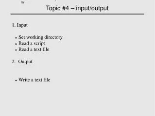
Circuit Design • Test Environment • Pulse generator converts clock signal to GasP ‘full’ states • Pulse Terminator makes it look like the downstream logic is always ‘empty’. • 4 square waves create an incrementing counter at the select input. • 16 Configuration data bits are constant
Agenda • Introduction & Motivation • Circuit Design • Results • Conclusion
Source Limited Operation • The source supplies data slower that the circuit can accept it. • Data only moves in the circuit when the source provides new data. • Data Output • The configuration RAM Bits = ‘1111 0000 1100 1010’ • 4-Stage Asynchronous output is shown. • The output from the other architectures is the same.
Source Limited Operation • 4-Stage 4LUT State Signals • Square wave is used to generate the first ‘full’ pulse • As each stage becomes full, the downstream stage accepts the data, and becomes full; the upstream stage is now empty. • The ‘full’ indication propagates from the first stage to the last stage as the data moves along.
Sink Limited Operation • The source supplies data faster that the circuit can accept it. • Data only moves in the circuit when the last stage becomes empty • 4-Stage 4LUT State Signals • The last stage becomes empty: data moves from the second last stage. • Second last stage is then empty: accepts data from the previous dstage • The ‘empty’ bubbles from the last stage up to the first
High Speed Operation • The source is supplying data and the sink is absorbing data as fast as the circuit can handle. • 2-Stage 4LUT State Signals • As soon as each stage becomes empty, new data is available. • Each stage spends as much time ‘empty’ as ful
High Speed Operation • 4-Stage 4LUT State Signals • There are multiple datum in the pipeline at any given time. • The blue lines touching the tops of the state waveform trace data as it flows through the 4LUT.
Performance Consumption • Performance results • The 4-Stage Synchronous architecture was found able to complete the most operations per second • The Synchronous design had a theoretical maximum of 7.7 GHz, providing the same throughput as the 2-stage Asynchronous LUT • A 2 or 4 stage synchronous design would be faster yet.
Power Consumption • Synchronous LE uses by far the least energy per calculation • Energy used is linear with respect to the number of GasP stages • About 3.7 pJ per GasP Stage • Does not account for the power consumed by the clock distribution network • Not required by the asynchronous architecture
Area Comparison • The 1-Stage GasP architecture and the Synchronous Architecture are alsmot the same size • 2 stage and 4 stage GasP architectures are 27% and 93% larger, respectively.
Agenda • Introduction & Motivation • Circuit Design • Results • Conclusion
Conclusion • GasP architectures were shown to work for 4-input lookup tables • 4-Stage and 2-Stage architectures were demonstrated • Source limited, sink limited, and control limited operation was observed • Energy consumption was found to be linear with the number of GasP stages • The energy consumption of a 1-Stage GasP architecture was found to be 7.8x that of the synchronous design. • Does not account for synchronous clock distribution. • Area was found for each architecture • The 1-Stage GasP and Synchronous Architecture are almost the same size. • 2 stage and 4 stage GasP architectures are 27% and 93% larger, respectively. • Conclusion • It is recommended that a GasP-based asynchronous FPGA built of 4-input lookup tables employ single-stage GasP 4LUTs as the basic logic building block. • This minimizes power consumption and area • Still allows a fine-grain micropipeline architecture, taking advantage of the promise of asynchronous logic design.
References [1] Sutherland, Ivan, and Fairbanks, Scott, “GasP: A minimal FIFO Control”, Synchronous Circuits and Systems, 2001. ASYNC 2001. Seventh International Symposium on , 11-14 March 2001 [2] Shams, Maitham, Ebergen, Jo, and Elmasry, Mohammed I. “Asynchronous Circuits”, http://citeseer.ist.psu.edu/495643.html [3] Ebergen, J, “Squaring the FIFO in GasP”, Asynchronous Circuits and Systems, 2001. ASYNC 2001. Seventh International Symposium on , 11-14 March 2001 [1] I. Sutherland, “Micropipelines”, Communications of the ACM, June 1989 [4] Girish Venkataramani, “Asynchronous Logic Design: What, Why and How?” National University of Singapore, Sept, 2004 [5] Myers, Chris J, “Asynchronous Circuit Design”, University of Utah lecture notes [6] A. Davis, S. Nowick, “An Introduction to Asynchronous Circuit Design”, University of Utah, Columbia University. [7] Asynchronous Logic Homepage http://www.cs.man.ac.uk/async/ [8] http://www.epson.co.jp/e/newsroom/2005/news_2005_02_09.htm [9] S.Brown, J. Rose, “Architecture of FPGAs and CPLDs: A Tutorial”, Department of Electrical and Computer Engineering, University of Toronto, 1994
Asynchronous GasP 4-Input Lookup Table Kent Orthner Wed. April 27th, 2005 Presentation for: High speed and Low Power VLSI, Dr. Maitham Shams