AIRFRAME
AIRFRAME. Objective. Know the design and construction features of the airframe and airframe components.

AIRFRAME
E N D
Presentation Transcript
AIRFRAME Objective Know the design and construction features of the airframe and airframe components.
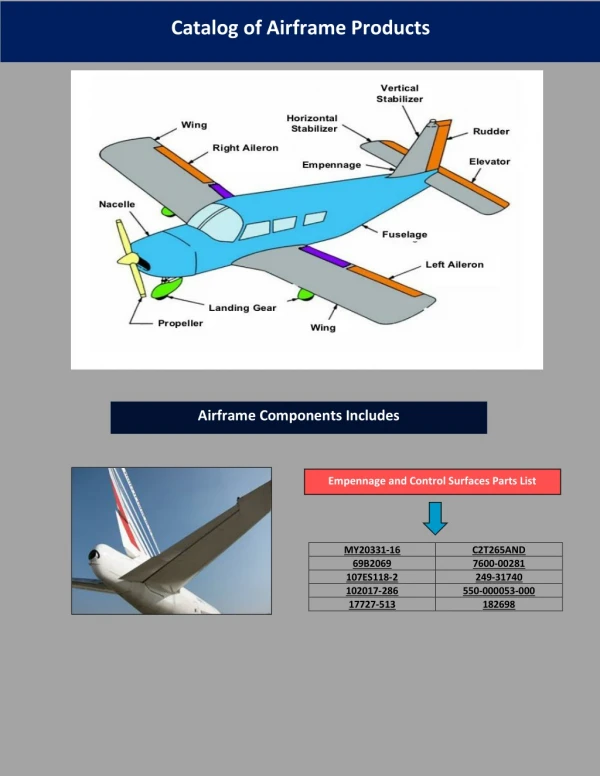
The forward section includes crew and passenger/cargo compartment, fuel cell enclosures, and pylon support. The intermediate section provides a deck for engine installation, a heater and electrical equipment compartment, and a baggage compartment. The tailboom includes the tail rotor system, horizontal stabilizer with auxiliary fins, elevator, and vertical fin.
CREW COMPARTMENT The forward portion of the cabin is utilized as the crew compartment. The pilot's station is located on the right side of the crew compartment. The left side of the crew compartment accommodates a passenger or copilot with the installation of the dual controls kit. The windshields are blue tinted acrylic panels and a minimum of structural obstructions give the occupants excellent visibility. Forward cabin doors are provided on both sides for direct access to these two stations. Each door is equipped with a horizontal adjustable window. Crew compartment door locks are provided.
PASSENGER / CARGO COMPARTMENT The cabin area aft of the crew compartment is utilized as the passenger/cargo compartment. Hinged entrance doors are provided on each side for entrance to the passenger/cargo compartment. Each door is approximately 36 inches wide by 39 inches high. The doors are hinged for forward opening. As a special feature, the left door is hinged at its forward edge, to a secondary (litter) door which in turn is hinged at its forward edge to the helicopter structure. The litter door is 25 inches wide and 39 inches high. The litter door opens only from the outside.
TAILBOOM The tailboom includes a fixed horizontalstabilizer with fixed leading edge slats, a controllable elevator, and a swept-back verticalfin. The horizontal stabilizer is installed on the tailboom and the elevator is installed on the horizontal stabilizer by means of antifriction bearings and bolts. The vertical fin extends from aft end of the tailboom and is canted to relieve tail rotor thrust requirements in forward flight. Auxiliary fins are mounted on the outboard ends of the horizontal stabilizer, and are canted to counteract yaw-roll. A tubular type tail skid is installed on the vertical fin to protect the tail rotor blades in the event of tail-low landings.
Slats Elevator
LANDING GEAR The landing gear assembly consists of two tubular aluminum alloy main skid tubes, two curved tubular aluminum alloy cross tubes, with optional airfoil type fairings on the forward and aft cross tubes. The landing gear is attached to the fuselage structure with four strap assemblies. Provisions are incorporated on the toe of each skid tube for standard tow bar attachment. Two eyebolts are installed on the skid tubes just forward of the aft cross tube for installing ground handling wheels. Each skid tube is provided with five replaceable skid shoes to absorb the wear caused by normal ground contact of the helicopter. A high skid gear kit, a fixed float kit, and an emergency flotation kit are available as optional equipment.
GROUND HANDLING WHEELS Dual ground handling wheels can be mounted on each skid tube near the helicopter center of gravity to facilitate handling or movement. The wheels are retract-ed and extended man-ually (hydraulically). Two 10 ply nylon tires with tubes are used on each assembly.
VENTILATION SYSTEM Fresh air ventilation to the interior is furnished through two large ram air scoops located on the upper nose of the ship, one on each side of the battery access door. Fresh air distributors along the bottom of the front windshield provide ventilation to the cabin in forward flight. The vents are opened or closed by pull handles located on the instrument console. In addition, all doors contain sliding plexiglas windows. An integral blower is a part of the system, and can provide approximately 70 cubic feet per minute during low speed conditions.