Download
1 / 20
1.24k likes | 3.12k Views
Airframe Description and Limitations. Cirrus SR22. Dimensions. SR22 G1/G2. SR22 G3. Fuselage. Composite Materials Composite roll cage integrated within fuselage structure Floors constructed of foam core composite to increase structural integrity of structure

E N D
AirframeDescription and Limitations Cirrus SR22
Dimensions SR22 G1/G2 SR22 G3
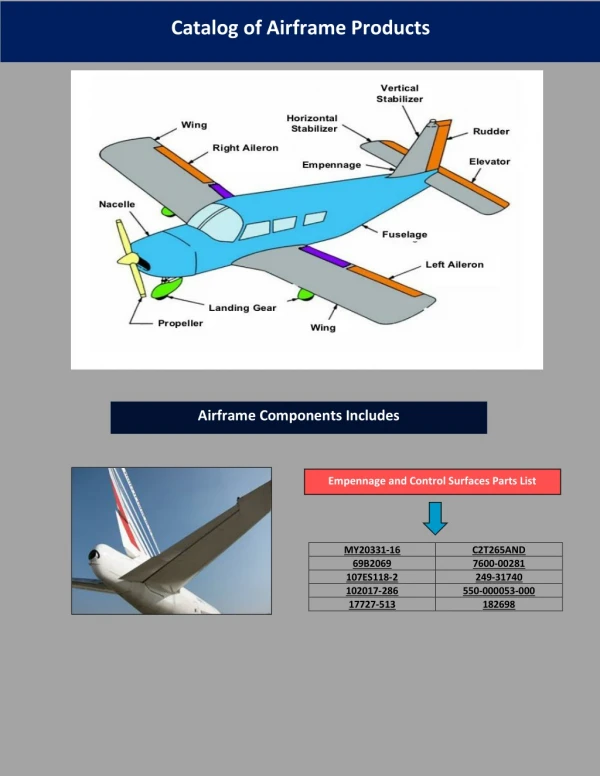
Fuselage • Composite Materials • Composite roll cage integrated within fuselage structure • Floors constructed of foam core composite to increase structural integrity of structure • Connected to wing spar through four wing attach points • Two points under front seats • Two points aft of rear seats
Cabin • Accommodates four adults • Front seats • Adjustable fore and aft • Recline or fold forward • 4-point seat belts • Airbags (late models) • Aluminum honeycomb core to absorb downward impact loads • Rear seats • Can be unlatched via pins in baggage compartment to accommodate larger baggage loads
Cabin • Cabin Doors • Secured by two latching pins located on the upper and lower portions of the door • Gas charged struts provide assisted door operation • Windshield and Windows • Manufactured of acrylic • Refer to POH section 8 for cleaning instructions • Baggage Compartment • Door located on left side of fuselage • Accessed via cabin door key • Tie-down straps and hooks available
Safety Equipment • Emergency Egress Hammer • Used to fracture acrylic windows to provide an escape path if upside down or if doors will not open • Fire Extinguisher • Halon 1211/1301 extinguishing agent • Class B (liquid, grease) and Class C (electrical) approved • 20 year useful life
Wings • Conventional rib and spar construction • Main wing spar is a continuous span from tip to tip • G1/G2 – Fiberglass • G3 – Carbon Fiber • Composite construction produces smooth and seamless surfaces • Wing cross section is a blend of multiple high performance airfoils
Vortex Generator • Vortex Generators • Disrupt airflow over the inboard portion of each wing at high angles of attack • Helps the inboard portion of the wing to stall prior to the outboard portion
Empennage • Horizontal and vertical stabilizers are single composite structures • Vertical Stabilizer structure is integrated into the main fuselage shell for smooth transfer of flight loads • Control surfaces are constructed from aluminum • Two-piece elevator • Rudder
Flight Control • Controls actuated through use of side control yokes and conventional rudder pedals • System uses a combination of push rods, cables and bell cranks for control actuation
Elevator System • Two piece control surface • Constructed of aluminum • Single cable runs under cabin floor to elevator
Aileron System • Constructed of aluminum • Single cable system runs under cabin floor and aft of the rear wing spar
Rudder System • Constructed of aluminum • Single cable runs under cabin floor to fuselage tailcone • Rudder-aileron interconnect • G1/G2 aircraft only • Provides maximum of 5° down aileron with full rudder deflection • Aileron control movement does not cause rudder movement • Ailerons bank in direction of rudder movement • Helps with low speed control • Not needed with G3 wing due to increase in wing dihedral
Wing Flaps • Single-slotted, aluminum • Electronically controlled • Actuator mechanically connected to both flaps by a torque tube • Proximity switches limit flap travel and provide position indication • Three settings indicated by illumination of LED’s adjacent to control • Flaps Up (0°) • Flaps 50% (16°) • Flaps 100% (32°)
Electronically actuated via conical trim button mounted on each side yoke Neutral positions (pitch & roll) indicated by markings on control yoke Trim is set by adjusting the neutral position of the spring cartridge of the appropriate flight control (elevator or aileron) Provides a secondary method of control actuation in the event of a linkage failure It is possible to easily override full trim or autopilot inputs by using normal control inputs Red A/P DISC button will interrupt trim in the event of a runaway trim incident Trim System
Main Gear • Constructed of composite material • Wheel pants are bolted to the struts and easily removable • Main gear tire • 15 x 6.00 x 6 • Inner tube type
Nose Gear • Constructed of tubular steel • Attached to the engine mount • Free castering • 216° of travel (108° either side of center) • Aircraft is controlled directionally through differential braking • Nose wheel tire • 5.00 x 5 • Inner tube type
Brake System • Hydraulically actuated, single-disc type brakes • Brakes are actuated through toe brakes on each rudder pedal • Parking Brake control closes valve holding hydraulic pressure against calipers • Do not activate the Parking Brake in flight • Temperature sensors are mounted on each brake assembly • Cirrus Perspective aircraft also display brake temperature warning annunciators on the PFD
Taxiing and Braking Techniques • Cirrus aircraft use a castering nose wheel • Directional control is accomplished with rudder deflection and intermittent braking (toe taps) as necessary • Normal braking during landing will not damage brakes • If aggressive braking is required, allow brakes to cool down prior to setting parking brake or performing more aggressive braking procedures • Use only as much power as is necessary to achieve forward movement • Reduce power to slow down and then apply brakes as necessary • Most common cause of brake damage and/or failure is due to improper braking practices • “Riding the brakes” while taxiing causes a continuous buildup of heat energy and increases the chance of brake failure or fire
Takeoff and Landing Techniques • Takeoff • At low airspeeds and power settings differential braking is required for directional control • At higher airspeeds and power settings rudder control is sufficient to provide directional control on the takeoff roll • Landing • Upon touchdown the rudder is initially used to maintain directional control • Once the aircraft stabilized on the runway apply even pressure to both brakes for directional control and brake as necessary