Download
1 / 78
870 likes | 1.53k Views
Gas Tungsten Arc Welding. Objectives. Describe the gas tungsten arc welding process List other terms used to describe it What makes tungsten a good electrode Eliminate tungsten erosion Shape and clean a tungsten electrode Grind a point on a tungsten electrode. Objectives (continued).

E N D
Objectives • Describe the gas tungsten arc welding process • List other terms used to describe it • What makes tungsten a good electrode • Eliminate tungsten erosion • Shape and clean a tungsten electrode • Grind a point on a tungsten electrode
Objectives (continued) • Remove a contaminated tungsten end • Melt the end of the tungsten electrode into the desired shape • Compare water-cooled GTA welding torches to air-cooled torches • The purpose of the three hoses connecting a water-cooled torch to the welding machine
Objectives (continued) • Choose an appropriate nozzle • How to get an accurate reading on a flowmeter • Compare the three types of welding current used for GTA welding • Shielding gases used in the GTA welding process
Objectives (continued) • Define preflow and postflow • Problems resulting from an incorrect gas flow rate • Properly set up a GTA welder • Establish a GTA welding arc
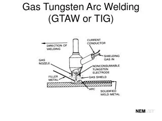
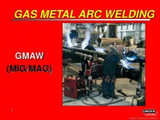
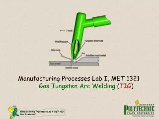
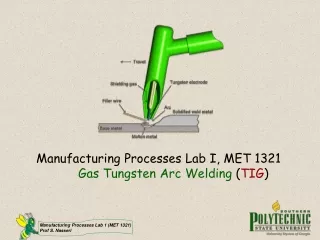
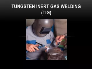
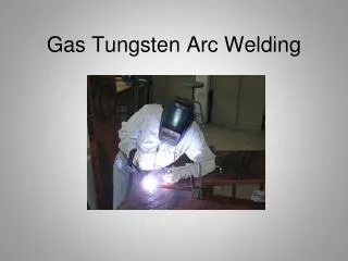
Introduction • The Gas Tungsten Arc Welding (GTAW) process is sometimes referred to as a TIG or Heliarc • TIG is short for tungsten inert gas • An arc is established between a non-consumable tungsten electrode (heating element) and the base metal • The inert gas provides the needed arc characteristics and protects the molten weld pool • When Argon became plentiful, the GTA process became more common
Tungsten • Tungsten has the following properties: • High tensile strength • Hardness • High melting temperature • High boiling temperature • Good electrical conductivity
Tungsten (continued) • Tungsten is the best choice for a non consumable electrode • High melting temperature • Good electrical conductivity • As the tungsten electrode becomes hot the arc between the electrode and the work stabilizes • But a clean and correctly ground tungsten is needed • Because of the intense heat some erosion of the electrode will occur
Figure 15-1 Some tungsten will erode and be transferred across the arc.
Tungsten (continued) • Ways to limit erosion: • Good mechanical and electrical contact • Use as low a current as possible • Use a water-cooled torch • Use as large a tungsten electrode as possible • Use DCEN current • Use as short an electrode extension as possible • Use the proper shape electrode • Use an alloyed tungsten electrode
Tungsten (continued) • The collet is the cone-shaped sleeve that holds the electrode in the torch • Large-diameter electrodes conduct more current • The current-carrying capacity at DCEN is about ten times greater than at DCEP • The preferred electrode shape impacts the temperature and erosion of the tungsten • With alternating current, the tip is subjected to more heat than with DCEN
Figure 15-3 The smooth surface of a centerless ground tungsten electrode. Courtesy of Larry Jeffus.
Types of Tungsten Electrodes • Pure tungsten is an excellent nonconsumable electrode • Pure tungsten can be improved by adding: • Cerium • Lanthanum • Thorium • Zirconium
Shaping the Tungsten • To obtain the desired end shape: • Grinding (for MS and SS) • Breaking (not recommended due to cost) • Re melting the end (Aluminium welding) • Using chemical compound (doesn’t work that well)
Grinding • Often used to clean a contaminated tungsten or to point the end • Should have a fine, hard stone • A coarse grinding stone with result in more tungsten breakage • Should be used for grinding tungsten only • Metal particles will quickly break free when the arc is started, causing contamination
Figure 15-8 Correct way of holding a tungsten when grinding. Courtesy of Larry Jeffus.
Breaking and Remelting • Tungsten is hard but brittle • If struck sharply, it will break without bending • Try not to do this because of $$$$$$$$ • Holding against a sharp corner and hitting results in a square break • After breaking squarely, melt back the end
Chemical Cleaning and Pointing • Tungsten can be cleaned and pointed using one of several compounds • Heated by shorting it against the work • Dipped in the compound • When the tungsten is removed, cooled, and cleaned, the end will be tapered to a fine point • The chemical compound will dissolve the tungsten, allowing the contamination to fall free
Pointing and Remelting • Tapered tungsten with a balled end is made by first grinding or chemically pointing • The ball should be made large enough so that the color of the end stays dull red and bright red • Increase ball size by applying more current • Surface tension pulls the molten tungsten up onto the tapered end
GTA Welding Equipment“Cadillac Stick Welder” • GTA welding torches are water- or air-cooled • Water-cooled GTA welding torch is more efficient • Water-cooled torch has three hosesconnecting it to the welding machine • Nozzle directs the shielding gas directly on the welding zone • Flowmeterregulates the rate of gas flow
Figure 15-21 Schematic of a GTA welding setup with a water-cooled torch.
Types of Welding Current • DCEN concentrates about 2/3 of its welding heat on the work • Max penetration • High Freq. – start only • DCEP concentrates about 1/3 of its welding heat on the work • Max cleaning action • 2/3 of heat at tungsten – primarily used for balling tungsten for aluminium welding • High Freq. – start only
Types of Welding Current • AC concentrates its heat at 50/50 • Sign wave provides for DCRP (cleaning action) and DCSP (penetration action) • Square wave technology allows for adjusting the cleaning or penetration cycle. • High Freq. is on Continuous so there is equal firing of both sides of sign wave. • DC Component will take place if there is no High Freq.
Figure 15-29 Electrons collect under the oxide layer during the DCEP portion of the cycle.
Shielding Gases • Shielding gases used for GTA welding process: • Argon (Ar) • Helium (He) • Or a mixture of two or more gases
Shielding Gases (continued) • Argon effectively shields welds in deep grooves in flat positions • Helium offers the advantage of deeper penetration
Shielding Gases (continued) • Hot start allows a surge of welding current • Preflow is the time gas flows to clear out air in the nozzle • Some machines do not have preflow • Postflow is the time the gas continues flowing after the welding current has stopped
Shielding Gases (continued) • Ionization Potential • Amount of voltage needed to “kick start” the arc • The ionization potential, or ionization energy, of a gas atom is the energy required to strip it of an electron. That is why a shielding gas such as helium, with only 2 electrons in its outer shell, requires more energy (higher voltage parameters) for welding. The ionization potential of a shielding gas also establishes how easily an arc will initiate and stabilize. A low ionization potential means the arc will start relatively easy and stabilize quite well. A high ionization potential has difficulty initiating and may have difficulty keeping the arc stable. • Argon • 15.7 electron volts • Helium • 24.4 electron volts • More penetration
Figure 15-35 Too steep an angle between the torch and work may draw in air.
Remote Controls • Can be used to: • Start the weld • Increase the current • Decrease the current • Stop the weld • Remote can be foot-operated or hand-operated device
Objectives • Applications using the gas tungsten arc welding process • Effects on the weld of varying torch angles • Why and how the filler rod is kept inside the protective zone of the shielding gas • How tungsten contamination occurs and what to do • Causes of change in welding amperage • Correct settings for the minimum and maximum welding current
Objectives (continued) • Types and sizes of tungsten and metal • Factors affecting gas preflow and postflow times • Minimum and maximum gas flow settings: • Nozzle size • Tungsten size • Amperage setting • Characteristics of low carbon and mild steels, stainless steel, and aluminum • Metal preparation for GTA welding • Make GTA welds in all positions
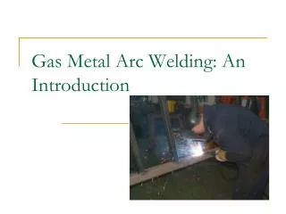
Introduction • Gas tungsten arc is also called GTA welding • GTA welding can be used to for nearly all types and thicknesses of metal • GTA welding is fluxless, slagless, and smokeless • Welders have fine control of the welding process • GTA welding is ideal for close-tolerance welds • Some GTA welds make the critical root pass • GTA used when appearance is important
Introduction (continued) • Setup of GTA equipment affects weld quality • Charts give correct settings • Field conditions affect the variables in the charts • Experiments designed to evaluate the appearance of a weld • After welding in the lab, troubleshooting field welding problems is easier • To make a weld is good: to solve a welding problem is better
Torch Angle • As close to perpendicular as possible • May be angled 0-15 degrees from perpendicular for better visibility • As the gas flows out it forms a protective zone around the weld • Too much tilt distorts protective shielding gas zone
Figure 16-5 Filler being remelted as the weld is continued. Courtesy of Larry Jeffus.