Download
1 / 27
300 likes | 693 Views
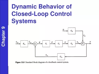
Toward Patient Safety in Closed-Loop Medical Device Systems . By- Rakheesh Kotagiri. Authors. Presentation flow. Introduction Understanding the Scenario & UPPAAL Architecture Verification and Validation of Components and System in Uppaal .

E N D
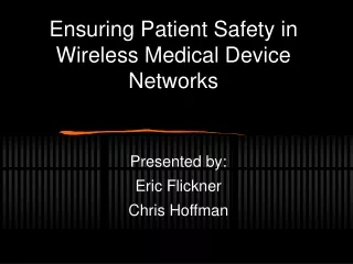
Toward Patient Safety in Closed-Loop Medical DeviceSystems By- RakheeshKotagiri
Presentation flow • Introduction • Understanding the Scenario & UPPAAL Architecture • Verification and Validation of Components and System in Uppaal. • MATLAB / SIMULINK MODELING OFSYSTEM DYNAMICS • Analysis of System Safety Properties • Failures and Fail-Safe PCA system
Introduction • Patient safety is the primary concern in the medical field, And the medical devices have to be very accurate in performance. • Caregivers role. • Medical devices made as CPS. • But still many Hospitals wont take the step to use these medical devices. • Reason for this is, When coming to the matter of human life, risk cannot be taken. • Accuracy, Performance, Sensing the behavior, every thing should be perfect.
CONT… • Government has to approve the medical devices by testing them. • In this paper we will see UPPAAL tool model, Which is used as a testing tool of medical devices. • This tool does not solve the problem but help to test the live environment scenarios, And make the improvements.
Understanding the Scenario & UPPAAL Architecture • Here we have PCA(Patient controlled analgesia), This is infusion pump. • It gives the facility to the patient to get pills according to his will. • Problem is overdose. • A well programmed PCA shouldn’t give the pills in overdose. • If any such problems or if the patient is feeling the suffocation even for small dose the system is built-in with supervisor kind of program.
Cont… • This shut downs the PCA and makes an alarm to the caregiver. • We use a pulse oximeter device, This is the clip on the patients finger. • This calculates heart beat and SpO2 outputs.
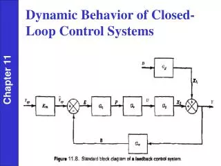
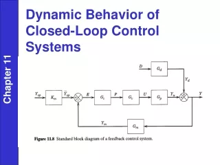
Communication Structure of the UPPAAL model Solid arrows represent communication Channels. Dashed arrows represent shared variables.
Verification and Validation of Components and System in Uppaal Uppsala University and Aalborg University • When pump in running state, pca_rate set to default rate • Or in state of bolusing when pca_rate increased by the bolus rate.
Cont… • Bolus_time parameter gives the time fixed duration for pumping pills. • Same as the PCA pump the pulse Oximeter has the timed automation. • Samples of Spo2 are obtained periodically with time interval of 1 unit. The result is showed in the po_result variable. • This po_result variable is delivered to the supervisor using the resultreadychannel.
The Supervisor automaton • Here the SPO2 readings are compared with the pre-defined threshold value. • If the results are too low, sends the stop message to the pump. • If there is any worst case execution time delay the caregiver resolves the problem and the supervisor sends the another message to restart the pump.
Patient & Network automation • Patient automation: Periodically updates the drug rate based on the flow rate of the pump and drug absorption rate. • Network Automation: It has two massages in the transit, one is the Stop message coming from the caregiver and the restart message.
Verifying PCA System Safety Properties • The main safety property that needs to be verified is the patient entering into the critical region. • In this we mainly concentrate on the SPO2 and heart rate readings. • : This means that is satisfied in every state. • : This means that is satisfied eventually along every path.
Cont.. • To check the pump is stopped if the patient ever enters the alarming region. • Finally checking the main safety property(critical region) • Critical region is set to 70%
MATLAB / SIMULINK MODELING OFSYSTEM DYNAMICS Drug flow is given by the drug absorption function. Patient model dynamics are modeled as a first order continuous system. The HR(heart rate) and SPO2 levels are extracted from the drug level using linear mapping.
Cont.. • The patient’s behavior is simulated based on the drug is repeatedly delivered for 10min followed by 10min pause. • The below fig represents the changes in HR and SPO2 levels. This results are displayed on patients monitors, and informs the supervisor.
Cont.. • Using the patient’s readings we define three different regions. • 1) safe region: This is the region where the patient’s reading are below threshold values that guarantee that patient’s vitals are not endangered.
Cont.. • Critical Region: This is the region where the patient’s life is in danger or there is a chance that irreparable damage can occur. • Alarming Region: This is the region where patient’s vitals are not damaged but there is a reasonable concern that the patient can be forced to the critical region.
Analysis of System Safety Properties • For the present system we consider the safety requirement that the PCA pump will always be stopped before patient’s critical region is reached. • Condition: • Tpodel: Worst case delay caused by PO. • Tnet: Worst case delay caused by network. • Tsup: Worst case delay caused by supervisor. • Tpump: Worst case delay caused by PCA pump. • Tp2po: Worst case latency from the moment when command is sent from PCA pump until the drug starts flowing.
Cont.. • Tpi: Worst case patient Inertia, a time that elapses before drug injected in body affects the patient. • Tcrit: Patient’s critical time, a shortest region before it enters critical region.
Cont.. • If the condition is satisfied we can guarantee that the supervisor will be able to determine that the patient have entered the alarming zone and stop PCA pump. • When the drug flow is on, HR and SPO2 level will decrease with time as function • To calculate tcrit consider t1(alarming) and t2(critical).
Failures and Fail-Safe PCA system • Here tdel takes into account all the delays in the loop and is defined as
Conclusion • In this paper a model driven approach to design and validate closed loop medical device system is presented. • This paper considered a simple relevant clinical model to discuss the validations. • In future this approach is suitable to implement the safety evaluation on more complicated medical devices.