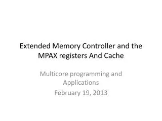
The Memory Controller
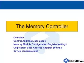
The Memory Controller. Overview Control/Address Lines usage Memory Module Configuration Register settings Chip Select Base Address Register settings Device considerations. Memory Controller Overview. BBUS. 32 Bit Address Bus 32 Bit Data Bus. Memory Controller. Bus Controller. NET+ARM.

The Memory Controller
E N D
Presentation Transcript
The Memory Controller Overview Control/Address Lines usage Memory Module Configuration Register settings Chip Select Base Address Register settings Device considerations
Memory Controller Overview BBUS 32 Bit Address Bus 32 Bit Data Bus Memory Controller Bus Controller NET+ARM 11 Direct Pins DATA BUS ADDRESS BUS • A28 : A0 • 256 Mbytes / Chip Select • SRAM and DRAM Supported • A13 : A0 Multiplexed • D32 : D0 • D31 : D24 8 Bit Device • D31 : D16 16 Bit Device • D31 : D0 32 Bit Device CONTROL LINES • Chip Select • Write Enable • Output Enable • Byte Enables • RAS • CAS External Bus Master • Bus Request • Bus Grant • Busy
RESET Memory Controller Hardware Dependencies RESET* Low for 512 Clocks Followed By 1 usec pulse Address Line Bootstrapping ADDR[24:23] CS0 Bootstrap Setting 00 Bootstrap Disabled 01 32-Bit SRAM port; 15 wait states 10 32-Bit DRAM port; 15 wait states 11 16-Bit SRAM port; 15 wait states A24 A23 The firmware MUST match the bootstrap setting Internal pull up constant current sources on Address Bus
Memory Controller Memory Map Register Address MMCR FFC0 0000 Chip Select 0 BAR FFC0 0010 Chip Select 0 OR FFC0 0014 Chip Select 0 ORB FFC0 0018 Chip Select 1 BAR FFC0 0020 Chip Select 1 OR FFC0 0024 Address Range Module Chip Select 1 ORB FFC0 0028 Chip Select 2 BAR FFC0 0030 0xFFC0 0000 0xFFCF FFFF MEM Module Chip Select 2 OR FFC0 0034 Chip Select 2 ORB FFC0 0038 Chip Select 3 BAR FFC0 0040 Chip Select 3 OR FFC0 0044 Chip Select 3 ORB FFC0 0048 Chip Select 4 BAR FFC0 0050 Chip Select 4 OR FFC0 0054 Chip Select 4 ORB FFC0 0058
28 27 19 16 31 30 29 26 25 24 23 22 21 20 18 17 RCYC AMUX A27 A26 RFCNT REFEN A25* AMUX2 12 11 3 0 15 14 13 10 9 8 7 6 5 4 2 1 - - - - - - - - - - - - - - - - 28 27 19 16 31 30 29 26 25 24 23 22 21 20 18 17 BASE 12 11 3 0 15 14 13 10 9 8 7 6 5 4 2 1 BASE PGSIZE DMODE DMUXS EXTTA IDLE DRSEL WP V DMUXM BURST 28 27 19 16 31 30 29 26 25 24 23 22 21 20 18 17 MASK 12 11 3 0 15 14 13 10 9 8 7 6 5 4 2 1 MASK WAIT BCYC BSIZE PS WP V Memory Module Configuration Memory Module Configuration Register (MMCR) FFC0 0000 Chip Select Base Address Register (CSBAR) [ FFC0 0010 FFC0 0040 ] Chip Select Option Register (CSOR) [ FFC0 0014 FFC0 0054 ]
MMCR RFCNT, REFEN, RCYC D24 D31 RFCNT Refresh Period = [ ( RFCNT + 1 ) * 4 ] / Fxtal Example: For a refresh period of 15.191usec, RFCNT must be 13 .. Assuming Fxtal = 3.6864MHz D23 REFEN REFEN Must be Set for DRAM Devices D22:21 RCYC Refresh Cycle Count 00 8 BCLK Clocks 01 6 BCLK Clocks 10 5 BCLK Clocks 11 4 BCLK Clocks NOTE: The NET+ARM DRAM Controller Always Generates CAS before RAS Refresh Cycles
MMCR AMUX External Multiplexer Externally Multiplexed Addresses Logical Addresses NET+ARM Address Pins DRAM PortC0 PortC1 PortC2 PortC3 / AMUX PortC4 / RIB* SEL RAS Address Driven CAS Address Driven D20 PORTC3 AMUX 0 Disable external PortC3 multiplexing 1 Enable external PortC3 multiplexing Lower Address Bits Upper Address Bits
MMCR AMUX2 D16 Internally Multiplexed Signals AMUX2 0 Normal Operation 1 Drive PortC3 DRAM Multiplexing NET+ARM DRAM Addresses External BUS Master DRAM PortC0 PortC1 PortC2 PortC3 / AMUX PortC4 / RIB* SEL • NOTES: • External bus master must have • the ability to multiplex RAS & CAS • addresses • Inactive bus master must • tri-state address bus • Drives PortC3 Multiplexing • Regardless of AMUX & DMUXS RAS Address Driven CAS Address Driven PORTC3 Lower Address Bits Upper Address Bits
MMCR A27, A26 NET+ARM NET+ARM Conventional Method Special Case Method GND VCC ADDR27/CS0OE* ADDR26/CS0WE* OE* WE* CS0* CS1*/RAS1* CS2*/RAS2* CS3*/RAS3* CS4*/RAS4* D19 A27 Enable A27 Output 0 CSO0E* Driven 1 ADDR 27 Driven Ground OE* WE* WE* OE* CE* CE* D18 FLASH FLASH A26 Enable A26 Output 0 CSOWE* Driven 1 ADDR 26 Driven Note: When used as special function, peripheral cannot ‘need’ A26 & A27
MMCR A25* A25* as Input is Burst Terminate Signal GND VCC ADDR27/CS0OE* ADDR26/CS0WE* ADDR25/BLAST* 0 1 A23 Memory Peripheral (X32) D17 External BUS Master A25* Enable A25 Output 0 Used for Address Line 25 1 Used for BLAST* Signaling Note: When used as special function, peripheral cannot ‘need’ A25 Burst Continuance Last Cycle of Burst BLAST*
CSAR BASE, PGSIZE, DMODE Sample NET+ARM Memory Space Physical Base Address of Peripheral D31 D12 BASE 0800 0000 • 0x00200 equates to 0x00200000 • BASE must be consistent with the size of the • MASK field in the Option Register • A 4M device MUST reside on a 4M Base Boundary FPGA D10 D11 Peripheral Page Size 0400 0000 PGSIZE 00 64 Bytes 01 32 Bytes 10 16 Bytes 11 8 Bytes FLASH 0200 0000 D9 D8 Page DMODE SDRAM 00 FP DRAM 01 EDO DRAM 10 Sync DRAM 11 RESERVED 0000 0000 NOTE: ALL DRAM BANKS MUST HAVE THE SAME DMODE SETTING
0 Internal Address Multiplexer 1 External Address Multiplexer IGNORED if AMUX or AMUX2 is set D7 DRAM Address Multiplexer Select DMUXS 0 Internal 1 External IGNORED if PS is set for 32 Bit Peripheral External TA* Configuration D6 EXTTA CSAR DMUXS, EXTTA, DMUXM 0 10 CAS 1 8 CAS MODE 1 Required for SDRAM DRAM Internal Multiplex Mode D5 DMUXM
CSAR IDLE, DRSEL, BURST, WP, V D4 • Force 1 BCLK at the End of the Memory Cycle • Can be useful for slower peripherals IDLE D3 Dynamic Ram Select Configures peripheral to operate in DRAM Mode Must be set for DMODE, DMUXS, and DMUXM WSYNC and RSYNC are ignored when DRSEL = 1 DRSEL D2 • Enable Burst Capability for Chip Select • Must be turned on to support Burst memory cycles BURST D1 • Write Protect Chip Select • Prevents any bus master from writing to the chip select • Useful for EEPROM and FLASH WP D0 • Valid Bit • V bit enables the chip select • ALL other BAR and CSOR settings must be valid V
CSOR MASK • Mask Determines the Physical Size of the Chip Select • Base and Mask used to decode what CS is activated Determining the MASK Setting for 16MBytes LSB of MASK MUST be 4K Physical Size Memory Peripheral XXXX XXXX XXXX XXXX XXX1 Therefore, extrapolation … 4KBytes XXXX XXX1 0000 0000 0000 16MBytes FF000 is MASK setting for 16MBytes on NET+Works Board Support Package 00FA 0000 0000 0000 + 16MBytes = 00FA 0000 SDRAM 0000 0000
CSOR Memory Aliasing with MASK FF000 = 1111 1111 0000 0000 0000 16MByte To Alias 4 Times on 64MByte Boundaries FF000 F3000 = 1111 0011 0000 0000 0000 16MByte BASE = 00000 0000 xx00 0000 0000 0000 = 0000 0000 0000 0000 0000 0100 0400 0000 1000 0800 0000 1100 0c00 0000 To Alias 8 Times on 128MByte Boundaries 88000 == F8000 == 1000 1000 0000 0000 0000 128MBytes BASE == 00000 == 00xx x000 0000 0000 0000 == 0000 0000 0000 0000 0000 0000 0000 1000 0800 0000 0001 0000 1000 0000 0001 1000 1800 0000 0010 0000 2000 0000 0010 1000 2800 0000 0011 0000 3000 0000 0011 1000 3800 0000 • Quick Notes: • 2(# of zeros) = # of repeats • Shift x bit right or left one position • to increase or decrease boundary
T1 T2 T1 T2 T1 BCLK CS0* T1 TW TW TW T2 WE* BCLK CS0* WE* CSOR WAIT Number of Wait States D8 D11 • Note: For DRAM and ASYNC SRAM • 0000 and 0001 yield the same result WAIT Number of Wait States IN ADDITION To 2 BCLKS 0 Wait States 3 Wait States
CSOR BCYC, BSIZE Number of Clocks for Subsequent Cycles For SDRAM D6 D7 CAS Latency BCYC BCYC Configuration 1 00 Controls the # BCLKS for Secondary Portion of the Burst 00 1 BCLK in Length (x,1,1,1) 01 2 BCLK in Length (x,2,2,2) 10 3 BCLK in Length (x,3,3,3) 11 4 BCLK in Length (x,4,4,4) 01 2 10 3 11 4 D4 D5 BSIZE Burst Length BSIZE 00 2 Words (Not Supported) 4 Words (Not Supported) 01 Maximum# of Memory Cycles that can Occur in a Burst 00 2 System Bus Cycles 01 4 System Bus Cycles 10 8 System Bus Cycles 11 16 System Bus Cycles 10 8 Words (Not Supported) Full Page 11 BSIZE is Configurable to ALL Settings Only after Load Mode Command
CSOR PS, RSYNC, WSYNC D2 Port Size D3 PS Defines the Physical Interface of the Memory Peripheral 00 32 Bit Port Size 01 16 Bit Port Size 10 8 Bit Port Size 11 32 Bit Port with External TA* PS Synchronous Mode Write Read Cycle Synchronous Mode D1 BCLK RSYNC CS0* Write Cycle Synchronous Mode D0 WE* WSYNC 0 SRAM in ASYNC Mode 1 SRAM in SYNC Mode Asynchronous Mode Write BCLK CS0* WE*
External SDRAM Multiplexing • SDRAM Write Command • SDRAM Read Command • SDRAM Load Mode Command • Driven on lower address lines • Required Configuration • AMUX ‘1’ • DMUXS ‘1’ • PORTC3 Special Function • Output CAS Address Driven For AMUX2 Usage While PORTC3 is low AND SDRAM issues ACTIVE Command ACTIVE is CAS[3:1] == {011} At ALL other Times, EBM Must Drive A23:A8. NET+50 Samples 1 BCLK Before PORTC3 to Examine Current SDRAM Page PORTC3 Lower Address Bits Upper Address Bits RAS Address Driven
Pin Configuration A13:0 CAS3* CAS2* CAS0* WE* Mode CSx* CAS1* OE* SRAM -- CS* -- -- -- -- OE* WE* FP Address RAS* CAS3* CAS2* CAS1* CAS0* OE* WE* EDO Address RAS* CAS3* CAS2* CAS1* CAS0* OE* WE* SDRAM Address CS* RAS* CAS* WE* A10/AP -- -- Other Address Lines are Driven with Logical Address A31:A28 (Internally) are copied from A27:A24
Bus Mapping D31 D24 D23 D16 D15 D8 D7 D0 32 Bit Data Bus Byte Enable 3 BE3* Byte Enable 2 BE2* Byte Enable 1 BE1* Byte Enable 0 BE0* 8-Bit Devices 16-Bit Devices 32-Bit Devices Address Bus Connections A28 A2 A1 A0 LSB for ALL 32 Bit Devices LSB for ALL 16 Bit Devices LSB for ALL 8 Bit Devices
NET+ARM to FLASH / SRAM Connections Figure 1 A0 A1 A2 A3 A4 A5 A6 A7 A8 A9 A10 A11 A12 A13 A14 A15 A16 A17 A18 CE* OE* WE* A1 A2 A3 A4 A5 A6 A7 A8 A9 A10 A11 A12 A13 A14 A15 A16 A17 A18 A19 D0 D1 D2 D3 D4 D5 D6 D7 D8 D9 D10 D11 D12 D13 D14 D15 D16 D17 D18 D19 D20 D21 D22 D23 D24 D25 D26 D27 D28 D29 D30 D31 SRAM / Conventional FLASH CSx OE* WE* CE* OE* WE* FLASH GROUND A27/CS0OE* A26/CS0WE* CE* OE* WE* NET+ARM Pins Figure 1 NOTE: Not All Signals Shown
NET+ARM to SDRAM Connections DEVICE 2 DEVICE 1 A2 A3 A4 A5 A6 A7 A8 A9 A10 A11 CAS0* A13 A22 A23 BE1* BE0* CAS1* CAS3* CAS2* CS/RAS* A0 A1 A2 A3 A4 A5 A6 A7 A8 A9 A10/AP A11 A12/BS1 A13/BS0 DQMU DQML WE* RAS* CAS* CS* D0 D1 D2 D3 D4 D5 D6 D7 D8 D9 D10 D11 D12 D13 D14 D15 D0 D1 D2 D3 D4 D5 D6 D7 D8 D9 D10 D11 D12 D13 D14 D15 A2 A3 A4 A5 A6 A7 A8 A9 A10 A11 CAS0* A13 A22 A23 BE3* BE2* CAS1* CAS3* CAS2* CS/RAS* A0 A1 A2 A3 A4 A5 A6 A7 A8 A9 A10/AP A11 A12/BS1 A13/BS0 DQMU DQML WE* RAS* CAS* CS* D0 D1 D2 D3 D4 D5 D6 D7 D8 D9 D10 D11 D12 D13 D14 D15 D16 D17 D18 D19 D20 D21 D22 D23 D24 D25 D26 D27 D28 D29 D30 D31 64M SDRAM 64M SDRAM NOTE: Not All Signals Shown
Static Memory Controller SRAM Memory Devices Memory Controller OE* Output Enable WE* Write Enable BE[3:0]* Byte Enables FPGA RW* Read / Write Strobe ADDR[28:0] Address Bus A/D Converters TA* Transfer Acknowledge TA* Transfer Acknowledge Myriad of SRAM Type Interface Devices Asynchronous SRAM cycles operate a minimum 1 wait state at ALL times
D31 : D0 A0 A0 A1 A1 A2 A2 Suggested Memory Subsystems 32 Bit SRAM (128K/256K x 32) 32 Bit SDRAM (2M x 32) 16 Bit Flash (512K x 16) System Bus D31 : D16 A0 D15 : D0 FLASH SRAM/SDRAM D15 : D0 A0 • SRAM (X32) • Pros • Extremely Fast • More Direct Interface • Suitable for Battery Backed Applications • Cons • Lower Densities • More $$ • Very efficient when used with FLASH executions w/ cache • SDRAM (X32) • Pros • More Density / $$ • Large Densities Available • Fairly fast • Cons • More Complex Interface • Timing is more Strict
Memory Controller Summary • Relevant registers • One global Memory Module Control Register • One Base Address Register and one options register per Chip Select • Control and Bus Controller’s address line usage is dictated by device characteristics • External SDRAM multiplexing possible via PORTC3