Download
1 / 69
690 likes | 880 Views
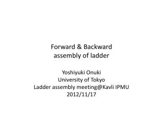
Forward & Backward assembly of ladder. Yoshiyuki Onuki University of Tokyo Ladder assembly meeting@Kavli IPMU 2012/11/17. SVD ladder assembly flow. Forward. Backward. Origami. Origami PA gluing. ← parallel( purural jigs).

E N D
Forward& Backwardassembly of ladder Yoshiyuki Onuki University of Tokyo Ladder assembly meeting@Kavli IPMU 2012/11/17
SVDladder assembly flow Forward Backward Origami Origami PA gluing ←parallel(purural jigs) DSSDs(rectangle、trapezoidal)are placed on the Assembly-bench with alignment Forwardassembly Backwardassembly Origami assembly ←parallel (independent each other) Gluing ribs time gluing Origamiand ribs
Procedure2: Placing DSSD with the the stopper Rough alignment with edge of DSSD. After the alignment, DSSD is vacuum chucked.
Procedure4:Placing the PAs on the PA-jigs.Dispensing glue. Small pins Small pins PAs are aligned by the pins and holes on the PA and the jigs. The method of dispensing glue is masking method.
Procedure5: Gluing the PAs We can observe the bonding pads on the PA with microscope while gluing.
Procedure6:Removing the PA-jig Before complete curing( ~1 hour after ), the PA-jig will be removed. The glue will automatically spread without any movement of PAs.
Procedure8: Placing the DSSD(-z) We can parallelize the procedure1~6 with plural set of jigs.
Procedure9: Placing the DSSD(CE) We can parallelize the procedure1~6 with plural set of jigs.
Procedure10: Placing the DSSD(+z) We can parallelize the procedure1~6 with plural set of jigs.
Procedure11: Placing the trapezoidal DSSD and the FW hybrid board The part where the trapezoidal DSSD and the FWHybrid are placed is removable from rib-jig. It has the vacuum chucking holes both the DSSD and the hybrid, separately.
Procedure12: Placing the BW DSSD(rectangle) and the hybridboard The part where the rectangle DSSD and the BWHybrid are placed is removable from rib-jig. It has the vacuum chucking holes both the DSSD and the hybrid, separately.
Procedure13: Placing the PE2 (FWand BW) In this figure, PE is aligned by hand. It may be better to make alignment holes as same as that of PA. In that case, PE should be aligned on the PE-jigs followed slides.
Procedure14: Placing the PE2-jig (FWand BW) PE2-jig has vacuum chucking holes. PE2 can be picked up with keeping alignment. Wire bonding pads on the APV25 side can be seen with microscope from top of the jigs while picking up the PE2. Although it become difficult design, it is better to make window to observe the pads on the DSSD side.
Procedure15: Dispensing glue on the PE2(FWand BW) Dispensing glue is done by masking method. As I mentioned, the alignment of PE2 should be done on the jig with pins and holes on the PE2 and PE2-jig.
Procedure16: Gluing the PE2 (FWand BW) Wire bonding pads can be seen with microscope from top of the jigs while picking up the PE2.
Procedure18:Lifting the assembly-bench to pick up the FW and BW part Where the place of FWand BWDSSD are sitting parts can be removable from the rib-jig. There are groove to contain the vacuum tube on the rib-jig. Once we should lift up the assembly-bench to remove the sitting parts
Procedure19: Wire bonding the PE2 and the DSSD(FW and BW) DSSD and hybrid board and PE2 are picked up on the part. These are moved to the wire-bonder and wire bonded.
Procedure20:Placing back the FW and BW on the assembly-bench. Placing back with reverse procedure.
Procedure21: Placing thepick-up-jig(FW and BW) Both pick-up-jig have the vacuum chucking holes for the DSSD and the hybrid. There are grooves to absorb the height difference of PE ,connector and hybrid.
Procedure22: Flipping the jigs There are grooves to absorb the height difference of bonding wire and connector.
Procedure23: Placing PE1(FW and BW) As I mentioned, the alignment of PE should be done on the jig with pins and holes on the PE1 and PE1-jig.
Procedure24: Placing PE1-jig(FW and BW) PE1-jigs are used to pick up the PE1. Although it become much difficult design since PE1 is too small, it is better to make window to observe the pads on the DSSD side.
Procedure25:Dispensing glue on the PE1(FW and BW) Dispensing with masking method.
Procedure27:Wire bonding the PE1 After removing PE1-jig and moving to the bonding machine, wire-bonding is done.
Procedure28:Placing back the FW part Placing back with reverse procedure.
Procedure30: Placing the slant-jig The slant-jig has the gonio stage to slant the torapezoidal DSSD. Also the slant-jig has the screws to fix the hybrid.
Procedure31:Vacuum chucking the trapezoidal DSSD with the slant-jig
Procedure32:Fixing the hybrid board to the slant-jig The DSSD are fixed with vacuum chucking. On the other hand, PEsand hybrid board are floating. We can bend the PEs according to the curvature of the jig. The slanted hybrid board is fixed by the screws on the slant-jig.
Procedure33:Lifting the slant-jig I am supposing to use the Z-stage to lift the slant-jig.
Procedure34: Origami part assembly Origami part assemblies can be started parallel after this procedure .
Procedure35:Slanting the gonio stage to the slant angle of the ladder
Procedure36: Placing rib-sitting-jig on the rib-jig Rib-sitting-jig
Procedure37:Placing the rib. Dispensing glue on the rib. The alignment of rib(+ mounting block) is determined as same as the way of ladder mounting on the end-ring.
Procedure46:Removing the pick-up jig(BW) Complete FWand BW assembly. Then after, combining Origami part