Download
1 / 47
470 likes | 581 Views
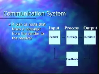
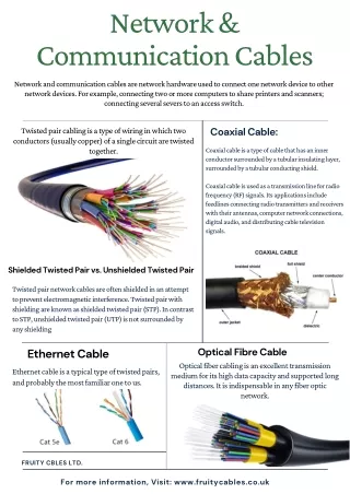
Learn all about Ethernet frames including frame types, destination & source addresses, FCS, OSI model, and ARP protocol in this comprehensive guide.

E N D
Ethernet IEEE 802.3 8 6 6 2 46 - 1500 4 Frame check Sequence (FCS) Destination address Source address Preamble Data Type Frame Header section Data section 4.1 Data Frame (Ethernet Frame)
Preamble – purposed for synchronization the frame reception portions of all stations on LAN. • Destination address – address of receiver (consist of 2 addresses : MAC address and IP address) • Source address – address of sender ( unicast address) • Type – specifies the upper layer protocol to receive the data after Ethernet processing is completed. • Data • FCS – contains 4-byte CRC (cyclical redundant check) value that is created by the sending device and is recalculated by the receiving device to check for damaged frame.
Ethernet frame. • Frames are the format of data packets on the wire. • Types of Ethernet frame: - Original Ethernet Version I (no longer used) - The Ethernet Version 2 or Ethernet II frame, known as DIX frame (named after DEC, Intel, and Xerox), often used directly by the Internet Protocol. - Novell's homegrown Variation of IEEE 802.3 ("raw 802.3 frame") without LLC - IEEE 802.2 LLC frame - IEEE 802.2 LLC/SNAP frame • In addition, Ethernet frames may optionally contain a IEEE 802.1Q tag to identify what VLAN it belongs to and its IEEE 802.1p priority (quality of service). This doubles the potential number of frame types. • The different frame types have different formats and MTU values, but it can coexist on the same physical medium.
The specifications of sections in the Ethernet Frames. Basic Ethernet frame forms.
Frame Header SectionIn a data packet sent through the internet, the data (payload) are preceded by header information such as the sender's and the recipient's IP addresses, the protocol governing the format of the payload and several other formats. The header's format is specified in the Internet Protocol. Frame check sequence (FCS) • A frame check sequence (FCS) refers to the extra checksum characters added to a Frame in a communication protocol for error detection and correction.
The sending host computes a checksum on the entire frame and sends this along. The receiving host computes the checksum on the frame using the same algorithm, and compares it to the received FCS. This way it can detect whether any data was lost on altered in transit. It may then discard the data, and request retransmission of the faulty frame. A cyclic redundancy check is often used to compute the FCS.
Address Resolution Protocol (ARP) Three types of address information are used on TCP/IP internetworks: • Physical addresses. Used by the Data Link and Physical layers. • IP addresses. Provide logical network and host IDs. IP addresses consist of four numbers typically expressed in dotted-decimal form. An example of an IP address is 134.135.100.13. • Logical node names. Identify specific hosts with alphanumeric identifiers, which are easier for users to recall than the numeric IP addresses. An example of a logical node name is MYHOST.COM.
Given a logical node name, the Address Resolution Protocol (ARP) can determine the IP address associated with that name. ARP maintains tables of address resolution data and can broadcast packets to discover addresses on the internetwork. The IP addresses discovered by ARP can be provided to Data Link layer protocols.
4.2 Open Systems Interconnection reference Model (OSI) • The OSI model divides the functions of a protocol into a series of layers. • Each layer has the property that it only uses the functions of the layer below, and only exports functionality to the layer above. • A system that implements protocol behavior consisting of a series of these layers is known as a 'protocol stack' or 'stack'. • Protocol stacks can be implemented either in hardware or software, or a mixture of both. • Typically, only the lower layers are implemented in hardware, with the higher layers being implemented in software.
Physical layer Layer 1: The physical layer defines all electrical and physical specifications for devices. • This includes the layout of pins, voltages, and cable specifications. Hubs and repeaters are physical-layer devices. • The major functions and services performed by the physical layer are: • establishment and termination of a connection to a communications medium. • participation in the process whereby the communication resources are effectively shared among multiple users. For example, contention resolution and flow control. • modulation, or conversion between the representation of digital data in user equipment and the corresponding signals transmitted over a communications channel. These are signals operating over the physical cabling -- copper and fibre optic, for example. SCSI operates at this level.
Data link layer Layer 2: The Data link layer provides the functional and procedural, - means to transfer data between network entities and to detect and possibly correct errors that may occur in the Physical layer. • The addressing scheme is physical which means that the addresses are hard-coded into the network cards at the time of manufacture. • The addressing scheme is flat. Note: The best known example of this is Ethernet. • Other examples of data link protocols are HDLC and ADCCP for point-to-point or packet-switched networks and LLC and Aloha for local area networks. • This is the layer at which bridges and switches operate. • Connectivity is provided only among locally attached network nodes.
Network layer Layer 3: The Network layer provides the functional and procedural - means of transferring variable length data sequences from a source to a destination via one or more networks while maintaining the quality of service requested by the Transport layer. • The Network layer performs network routing, flow control, segmentation/desegmentation, and error control functions. • The router operates at this layer -- sending data throughout the extended network and making the Internet possible, although there are layer 3 (or IP) switches. • This is a logical addressing scheme - values are chosen by the network engineer. • The addressing scheme is hierarchical.
Transport layer Layer 4: The purpose of the Transport layer is to provide transparent transfer of data between end users - thus relieving the upper layers from any concern with providing reliable and cost-effective data transfer. • The transport layer controls the reliability of a given link. • Some protocols are stateful and connection oriented. • This means that the transport layer can keep track of the packets and retransmit those that fail. • The best known example of a layer 4 protocol is TCP.
Session layer Layer 5: The Session layer provides the mechanism for managing the dialogue between end-user application processes. • It provides for either duplex or half-duplex operation and establishes checkpointing, adjournment, termination, and restart procedures. • This layer is responsible for setting up and tearing down TCP/IP sessions.
Presentation layer Layer 6: The Presentation layer relieves the Application layer of concern regarding syntactical differences in data representation within the end-user systems. • MIME encoding, encryption and similar manipulation of the presentation of data is done at this layer. • An example of a presentation service would be the conversion of an EBCDIC-coded text file to an ASCII-coded file.
Application layer Layer 7, the highest layer: This layer interfaces directly to and performs common application services for the application processes. • The common application services provide semantic conversion between associated application processes. • Examples of common application services include the virtual file, virtual terminal (for example, Telnet), and "Job transfer and Manipulation protocol" (JTM, standard ISO/IEC 8832).
The connection between OSI model & the protocol • Above illustrates the origin of the term protocolstack. • Each layer represents a category of related tasks. • A protocol stack is an implementation of this layered protocol architecture. • The protocols and services associated with the protocol stack interact to prepare, transmit, and receive network data.
Two computers must run compatible protocol stacks before they can communicate because each layer in one computer’s protocol stack must interact with a corresponding layer in the other computer’s protocol stack.
The FIGURE, for example, shows the path of a message that starts in the Transport layer. • The message travels down the protocol stack, through the network medium, and up the protocol stack of the receiving computer. • If the Transport layer in the receiving computer understands the protocols used in the Transport layer that originated the message, the message can be delivered.
The concept of layered protocol. • To communicate with its peer layer in another computer, each protocol layer adds its own information to the message being sent. • Headers are added as the message is prepared for transmission, and headers are removed (stripped) by the receiving computer after the information in the header has been utilized. *NOTE • The Physical layer does not append a header because this layer deals with sending and receiving information on the individual bit level. The bits are assembled into longer message units in the Data Link layer.
Each protocol layer, except the Physical layer, adds a header to the frame.
TCP / IP • Also called internet protocol suite which it is the set of communications protocols that implement the protocol stack on which the Internet runs • TCP/IP working each other together and provide the basis for much of the Internet.
A combination of two individual protocols: TCP and IP. • IP is a layer 3 protocol – a connectionless service that provides best-effort (nonreliable) delivery across a network. • TCP is a layer 4 protocol – a connection-oriented service that provides flow control as well as reliability. • Combination of two protocols (TCP + IP) enables them to provide a wider range of services.
TCP/IP vs OSI • The OSI model - lower layers - needs to be an extra layer (the Internetworking layer) between the Transport and Network layers. • The top three layers of the OSI model (Application, Presentation and Session) - considered as a single Application Layer in the TCP/IP suite. • TCP/IP integrates a few steps of the OSI model into its Application layer. • The TCP/IP suite protocols as developed earlier than OSI reference model by DARPA (Defense Advanced Research Projects Agency) for internetwork communications and serves as the transport protocols for the internet
Internet Address • An IP address (Internet Protocol address) is a unique number, similar in concept to a telephone number, used by machines (usually computers) to refer to each other when sending information through the Internet
IP address • Represented by a 32-bit binary number written as four octets Octet (8 bits) ● Octet (8 bits) ● Octet (8 bits) ● Octet (8 bits) 27262524232120 ● 27262524232120 ● 27262524232120 ● 27262524232120 11000000 ● 00000101 ● 00100010 ● 00001011 EQUALS 192 ● 5 ● 34 ● 11
The maximum decimal value of each octet is 255. • The largest 8-bit binary number is 11111111. • Those bits, from left to right, have decimal values of 128, 64, 32, 16, 8, 4, 2, 1. Added, they total 255.
IP addressing format • An IP address has a network number and a host number, and uses dotted-decimal notation.
IP address classes • The network number of IP address identifies the • network to which a device is attached . • The host portion of IP address identifies a specific • device on a network.
Class A • Support extremely large networks • First octet of Class A IP address recognize with range 1 to 126. (127 does start with a 0 bit, but it has been reserved for special purposes. • The first bit of class A address always 0 in binary format. • Class A IP addresses use only the first 8 bits (1 octet) to identify the network part of the address.
The remaining three octets (24 bit) can be used for the host portion of the address. • Every network that uses a Class A IP address can be assigned up to 224– 2 possible IP addresses to devices attached to the network. • Example of Class A IP address : 124.95.44.15
Class B • Support the needs of moderate to large sized networks. • The first 2 bits of Class B IP address are always 10 (1 and 0) • The first two octets identify the network number assigned by ISP. • Class B IP network addresses always have values ranging from 128.0.0.0 to 191.255.0.0.
Class B IP addresses use the first 16 bits (2 octets) to identify the network part of the address. • The two remaining octets of the IP address can be used for the host portion of the address. • Every network that uses a Class B IP address can have assigned up to 216 – 2 possible IP addresses to devices attached to the network. • Example of Class B IP address: 151.10.13.28
Class C • Most commonly used of the original IPv4 address classes. • This address space was intended to support a small network. • The first 3 bits of a Class C address are always 110 (1,1,and 0). • The first three octets identify the network number assigned by ISP. • Class C IP network addresses always have values ranging from 192.0.0.0 to 223.255.255.0
Class C IP addresses use the first 24 bits (3 octets) to identify the network part of the address. • Only the last octet of a Class C IP address can be used for the host portion of the address. • Every network that uses a Class C IP address can have assigned up to 28 – 2 possible IP addresses to devices attached to the network • Example of a Class C IP address : 201.110.213.28
Subnet • Network administrators sometimes need to divide networks, especially large ones, into smaller networks. • These smaller divisions are called subnetworks and provide addressing flexibility. • The concept of subnetting is based on the need for the third level in the Internet’s addressing hierarchy. • A primary reason for using subnets is to reduce the size of a broadcast domain. • Subnet addresses includes the network number, subnet number and host number.
Subnetworks • subnet addresses include the class A , class B, or class C network portion, plus a subnet field and a host field. • The subnet field and the host field are created from the original host portion for the entire network. • To create a subnet address, a network administrator borrows bits from the original host portion and designates them as the subnet field. • The minimum number can be borrowed is 2.