Download
1 / 3
30 likes | 57 Views
The solar adsorption Refrigeration system is very useful in rural area without grid. The Adsorber desorber are the important role in this system. Among the adsorbent refrigerant, the activated carbon and ethanol is applied. This paper focuses on the adsorption time of adsorber bed with constant thickness. Soe Soe Nu | Dr. Mi Sandar Mon "Analysis of Adsorption Time for Solar Adsorption Refrigeration System" Published in International Journal of Trend in Scientific Research and Development (ijtsrd), ISSN: 2456-6470, Volume-2 | Issue-6 , October 2018, URL: https://www.ijtsrd.com/papers/ijtsrd18349.pdf Paper URL: http://www.ijtsrd.com/engineering/mechanical-engineering/18349/analysis-of-adsorption-time-for-solar-adsorption-refrigeration-system/soe-soe-nu<br>

E N D
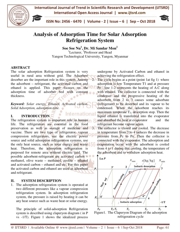
International Journal of Trend in International Open Access Journal International Open Access Journal | www.ijtsrd.com International Journal of Trend in Scientific Research and Development (IJTSRD) Research and Development (IJTSRD) www.ijtsrd.com ISSN No: 2456 ISSN No: 2456 - 6470 | Volume - 2 | Issue – 6 | Sep | Sep – Oct 2018 Analysis of Adsor Adsorption Time for Solar Adsorption Solar Adsorption Refrigeration System Refrigeration System Soe Soe Nu1, Dr. Mi Sandar Mon2 1Lecturer, 2Professor and Head Yangon Technological University,Yangon, Myanmar Soe Soe Nu Yangon Technological University ABSTRACT The solar adsorption Refrigeration system is very useful in rural area without grid. The Adsorber/ desorber are the important role in this system. Among the adsorbent – refrigerant, the activated carbon and ethanol is applied. This paper focuses on the adsorption time of adsorber bed with constant thickness. Keyword: Solar energy, Ethanol, Activated carbon, Solid Adsorption, adsorption time. I. INTRODUCTION The refrigeration system is important role in human life. The refrigerators are essential in the food preservation as well as storage of medicine and vaccine. There are two type of refrigerator, vapour compression refrigerators, use the electric power source and solid adsorption refrigeration systems, use the only heat source, such as solar energy and waste heat. Therefore, the adsorption refrigeration is purposed for remote area without electric grid. The possible adsorbent-refrigerant are activated carbon methanol, olive waste – methanol, zeolite and activated carbon – ethanol and etc. For this paper the activated carbon and ethanol are used as adsorbent and refrigerant. II. SYSTEM DESCRIPTION 1.The adsorption refrigeration system is operated at two different pressures like a vapour compression refrigeration system. In adsorption refrigeration system, the pressure is raised by heating it can be any heat source such as waste heat or solar energy. The principle of solid-adsorption Refrigeration system is described using claperyon diagram ( in P vs -1/T). Figure 1 shows the idealized process 1/T). Figure 1 shows the idealized process undergone by Activated Carbon and ethanol in achieving the refrigeration effect. 2.The cycle begins at a point adsorption is low Temperature T1 and at pressure Pe . line 1-2 represents the heating of A.C along with ethanol. The collector is connected with the condenser and the progressive heating of the adsorbent from 2 to 3 causes some adsorbate (refrigerant) to be desorbed and its vapour to be condensed. When the adsorbent reaches its maximum temperate T3, desorption stop. Then the liquid ethanol is transferred into the evaporator and absorbed the heat at evaporator refrigerant become vapour again. 3.The collector is closed and cooled. The decrease in temperature from 3 to 4 induces the decrease in pressure from Pc to Pe. Then the collector is connected with the evaporator. The adsorption and evaporation occur with the adsorbent is cooled from 4 to 1 during this cooling, the temperature of the adsorbent and to withdraw adsorption heat. the adsorbent and to withdraw adsorption heat. The solar adsorption Refrigeration system is very useful in rural area without grid. The Adsorber/ undergone by Activated Carbon and ethanol in achieving the refrigeration effect. The cycle begins at a point (point 1at fig 1) where dsorption is low Temperature T1 and at pressure 2 represents the heating of A.C along with ethanol. The collector is connected with the condenser and the progressive heating of the adsorbent from 2 to 3 causes some adsorbate desorbed and its vapour to be condensed. When the adsorbent reaches its , desorption stop. Then the liquid ethanol is transferred into the evaporator and absorbed the heat at evaporator refrigerant become vapour again. lector is closed and cooled. The decrease in temperature from 3 to 4 induces the decrease in pressure from Pc to Pe. Then the collector is connected with the evaporator. The adsorption and evaporation occur with the adsorbent is cooled his cooling, the temperature of this system. Among refrigerant, the activated carbon and ethanol is applied. This paper focuses on the adsorption time of adsorber bed with constant Solar energy, Ethanol, Activated carbon, The refrigeration system is important role in human life. The refrigerators are essential in the food preservation as well as storage of medicine and vaccine. There are two type of refrigerator, vapour and the the electric power source and solid adsorption refrigeration systems, use the only heat source, such as solar energy and waste heat. Therefore, the adsorption refrigeration is purposed for remote area without electric grid. The nt are activated carbon – methanol, zeolite – ethanol ethanol and etc. For this paper the activated carbon and ethanol are used as adsorbent n system is operated at two different pressures like a vapour compression refrigeration system. In adsorption refrigeration system, the pressure is raised by heating it can be any heat source such as waste heat or solar energy. rption Refrigeration Figure1. The Claperyon Diagram of the refrigeration cycle refrigeration cycle 1. The Claperyon Diagram of the adsorption system is described using claperyon diagram ( in P @ IJTSRD | Available Online @ www.ijtsrd.com www.ijtsrd.com | Volume – 2 | Issue – 6 | Sep-Oct 2018 Page: 61
International Journal of Trend in Scientific Research and Development (IJTSRD) ISSN: 2456 International Journal of Trend in Scientific Research and Development (IJTSRD) ISSN: 2456 International Journal of Trend in Scientific Research and Development (IJTSRD) ISSN: 2456-6470 III. ANALYSIS ADSORBER BED Mass concentration or mass density: The mass concentration of the component A within a multi component mixture is defined as mass of species A per unit volume of the mixture under consideration. It is denoted by ?? and is expressed in?? Mass concentration ?? ? Molar concentration: The molar concentration of the component A is defined as the number of moles of species A per unit volume of mixture. It is also called molar density and denoted by ?? and expressed in ??.???/??. The molar concentration, ???No.of moles of component Volume of mixture Number of moles of component: ???Mass of component A Molecular weight of A? Therefore, molar concentration, Mass of component A Volume of mixture ? M? where MA = molecular weight of component A. Mass fraction: The mass fraction ?? is defined as the ratio of mass concentration of species A to the mass density ρ, of mixture, ????? ANALYSIS ON ON ADSORPTION ADSORPTION AT AT the mixture. The total pressure of a mixture is the summation of partial pressures of all components in the mixture, ? ? ??? ??? ?? For a binary mixture of component A and B, the following summation rules may be applied. ??? ??? ? ??? ??? ? ??? ??? 1 ??? ??? 1 ?? Where ρ, C, M are the quant mixture ????? RT? ?°? A ` pressure of a mixture is the summation of partial pressures of all components in Mass concentration or mass density: The mass concentration of the component A within a multi component mixture is defined as mass of species A per unit volume of the mixture under consideration. It ??? ⋯? ?? ??/??. For a binary mixture of component A and B, the following summation rules may be applied. ???? ?? ????????? ? ?????? ?? ???????? ?? ? ? Molar concentration: The molar concentration of the component A is defined as the number of moles of species A per unit volume of mixture. It is also called ?? ??? ? ? ??? and expressed in , C, M are the quantities pertaining to the component A??? M??? R?T ? M? R?T ??? ?? ? ?D??R ??? M? ? ? ? ? ???? ? ? ? ? ? ? D??? 435.7 ? ? ??? ?? ? ?? Therefore, molar concentration, ???? Where DAB = diffusion coefficient, cm T = absolute temperature, K P = total pressure of system, N/m VA = molecular volume of component A VB = molecular volume of component B MA = molecular weight of component A MB = molecular weight of component B The one dimensional molar diffusion, The one dimensional molar diffusion, = diffusion coefficient, cm2/s ??? M? ??? system, N/m2 or Pa = molecular volume of component A = molecular volume of component B = molecular weight of component A = molecular weight of component B = molecular weight of component A. is defined as the ratio of mass concentration of species A to the mass C - C A= N D A1 A1 A2 AB L ? IV. The mass flow rate of refrigerant is constant and the pressure of evaporator and adsorber are same. The length of adsorber bed is divided into six sections. Moreover, the refrigerant at the entrance of absorber is absorbed immediately by the first section. concentration at the adsorber bed is zero. In here, Subscript A represents refrigerant and B represents activated carbon. The evaporation time for one cycle is 10 min. DESIGN CONSIDERATION DESIGN CONSIDERATION The mass flow rate of refrigerant is constant and the pressure of evaporator and adsorber are same. The length of adsorber bed is divided into six sections. Moreover, the refrigerant at the entrance of absorber is absorbed immediately by the first section. The concentration at the adsorber bed is zero. In here, Subscript A represents refrigerant and B represents activated carbon. The evaporation time for one cycle Mole fraction. It is defined as the ratio of number of moles of component A to the total number of moles of mixture. It is denoted by ?? and expressed as: ????? Partial pressure: It is defined as the pressure exerted by a single component in a mixture, when it exits alone in the system at the temperature and volume of Mole fraction. It is defined as the ratio of number of moles of component A to the total number of moles of and expressed as: ? Partial pressure: It is defined as the pressure exerted by a single component in a mixture, when it exits alone in the system at the temperature and volume of @ IJTSRD | Available Online @ www.ijtsrd.com www.ijtsrd.com | Volume – 2 | Issue – 6 | Sep-Oct 2018 Page: 62
International Journal of Trend in Scientific Research and Development (IJTSRD) ISSN: 2456 International Journal of Trend in Scientific Research and Development (IJTSRD) ISSN: 2456 International Journal of Trend in Scientific Research and Development (IJTSRD) ISSN: 2456-6470 V. This research is performed for 500 W of evaporator. The useful data and some assumption are shown in the following table. Table1. Design Data Evaporator load (W) Evaporator temperature (C) Evaporator pressure (MPa) The mass flow rate of refrigerant (kg/sec) The mass of activated carbon (kg) Volume of activated carbon (cm3) The thickness of adsorbent (cm) The length of adsorbent (cm) VI. RESULT AND DISCUSSION The adsorber bed is divided into six sections. The calculation is performed only first section, the of section is 5 cm. Therefore the length of first section is 5 cm. the following results are obtained, shown in Table 2. Table2 Results of adsorbent bed. Mass diffusion coefficient Rate of molar diffusion THE DESIGN ASSUMPTION THE DESIGN ASSUMPTION This research is performed for 500 W of evaporator. seful data and some assumption are shown in ACKNOWLEDGMENT The author would like to thank to my supervisor, Dr. Mi Sandar Mon, Professor and Head of Mechanical Engineering Department, Yangon Technological University who is a special guidance for me. The special thanks go to DEEM (Development of Energy Engineering Mekong) project. REFERENCES 1.K. Sumathy and Li Zhongfu ,“ Experimental with solar-powered adsorption Department of Mechanical University of Hong Kong , Hong Kong, 1 2.Nadal H. Abu-Hamdeh, Khaled A. Alnefaie, Khalid H. Almitani, “ Design and performance characteristic of solar adsorption refrigeration system using parabolic Experimental and technique,” 3.A. M. Abu-Zour, S. B. Riffat, “Solar conditioning Cycle: A Review,” The Journal of Engineering Research vol.4, no.1 63. 4.V. Baiju and C. Muraleedharan, “Performance of Solar Adsorption Refrigeration system by Ann,” ISRN Thermodynamics, vol 2012, Artic 102376, 5.A. V. Kanade, A. V. Kulkarni, D. “solar power Adsorption Ice Maker System,” International Research Journal of Engineering and Technology(IRJET). 6.Mashesh M. Rathore, “Engineering Heat and Mass Transfer” Third Edition, (2016), Uni Science Press. The author would like to thank to my supervisor, Dr. Mi Sandar Mon, Professor and Head of Mechanical Engineering Department, Yangon Technological University who is a special guidance for me. 500 5 0.0021 The special thanks go to DEEM (Development of Energy Engineering Mekong) project. 0.000531 Sumathy and Li Zhongfu ,“ Experimental with powered adsorption Department of Mechanical University of Hong Kong , Hong Kong, 1999. ice Engineering, Engineering, ice-maker,” 3.8232 9558 10 30 Hamdeh, Khaled A. Alnefaie, Khalid H. Almitani, “ Design and performance characteristic of solar adsorption refrigeration system using parabolic Experimental and trough trough collector: optimization optimization collector: statistical statistical The adsorber bed is divided into six sections. The calculation is performed only first section, the length of section is 5 cm. Therefore the length of first section is 5 cm. the following results are obtained, shown in . Riffat, “Solar-Driven Air- conditioning Cycle: A Review,” The Journal of Engineering Research vol.4, no.1, 2007, pp. 48- Results of adsorbent bed. 2.1 x10⁻⁴ D AB (cm2/s) NA kg- mole/s m˙A (kg/s) m (kg) V. Baiju and C. Muraleedharan, “Performance of Solar Adsorption Refrigeration system by Ann,” ISRN Thermodynamics, vol 2012, Article ID 3.048 x10⁻³ 0.14 0.3186 Mass diffusion rate Mass of refrigerant for one cycle Adsorption time for one cycle V. Kulkarni, D. A. Deshmukh, “solar power Adsorption Ice Maker System,” International Research Journal of Engineering and t (s) 2.3 VII. It is found that the first section of absorber can absorb the refrigerant easily because the rate of mass refrigerant to be absorbed is greater than the flow rate of refrigerant from evaporator. The calculation will be ahead for other sections. The thickness of adsorber 10 cm is suitable for this system. In this system the flow is one dimensional, downward. The evaporation time for one cycle is 10 min and the adsorbtion time is 2.3 second for one cycle. In conclusion, it is satisfied that the adsorption time is faster than evaporation time. The forward dimensional should be considered. Moreover, the two and three dimensional also should be considered. Mashesh M. Rathore, “Engineering Heat and Mass Transfer” Third Edition, (2016), University CONCLUSION It is found that the first section of absorber can absorb the refrigerant easily because the rate of mass of refrigerant to be absorbed is greater than the flow rate of refrigerant from evaporator. The calculation will be ahead for other sections. The thickness of adsorber 10 cm is suitable for this system. In this system the flow . The evaporation time for one cycle is 10 min and the adsorbtion time is 2.3 second for one cycle. In conclusion, it is satisfied that the adsorption time is faster than evaporation time. The forward dimensional should be considered. and three dimensional also should @ IJTSRD | Available Online @ www.ijtsrd.com www.ijtsrd.com | Volume – 2 | Issue – 6 | Sep-Oct 2018 Page: 63


![protein adsorption [%]](https://cdn3.slideserve.com/5518059/slide1-dt.jpg)